
[Lynx] RetroSix CleanScreen
This guide covers installing the CleanScreen V3 in the Atari Lynx I. The CleanScreen fits the original shell, no shell modification is needed. The install does require extensive soldering and wire.
Preparation
Section titled “Preparation”Before you install the CleanScreen, make sure the system is fully working.
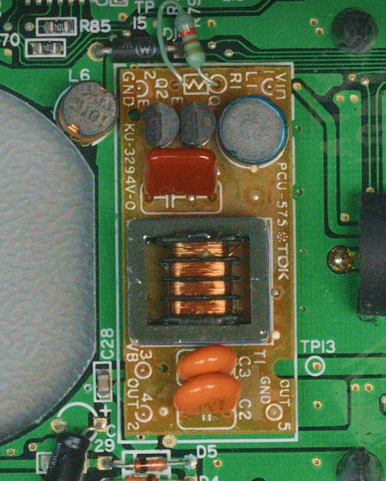
The next step is technically optional but highly recommended: remove the high voltage driver board. That way you don’t end up with high voltages on a system that no longer needs them, and you don’t zap yourself while installing.
Mounting the LCD and PCB
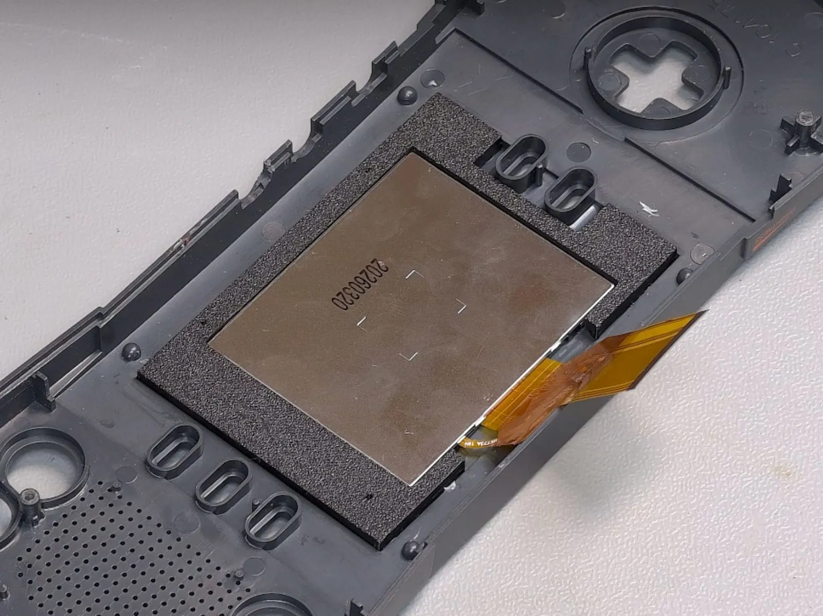
Section titled “Mounting the LCD and PCB”Place the 3D bracket and the LCD in position. You can secure them with a tack of hot glue or epoxy, or put double-sided foam over the top so that the PCB holds the screen where it needs to be once you place it back.
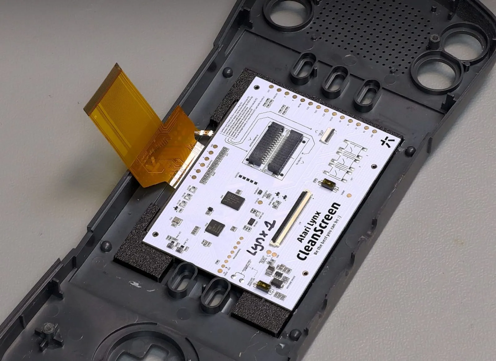
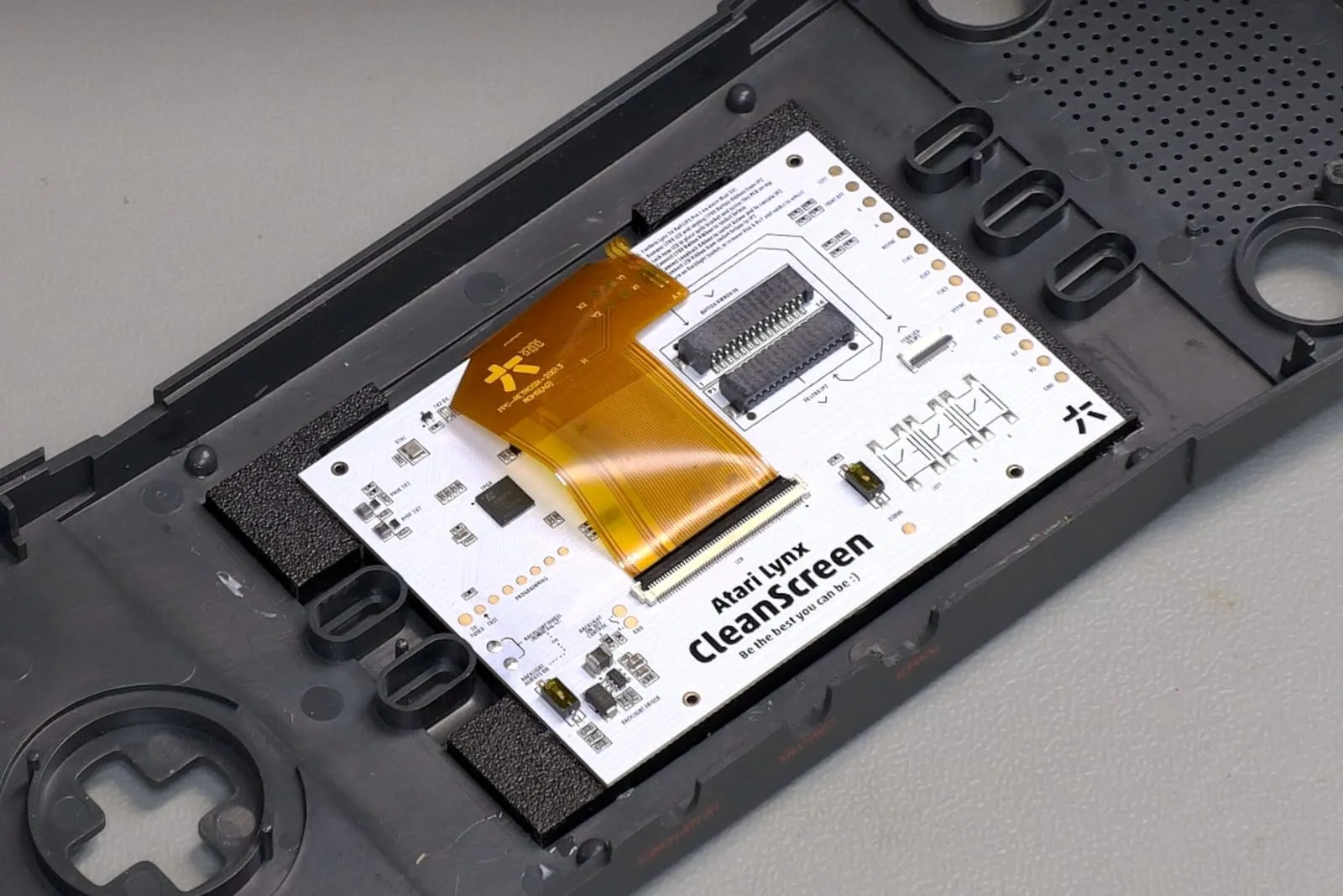
Now place the CleanScreen PCB over the screen in the orientation shown. The LCD’s flex ribbon should line up with the PCB pins. Secure the PCB either with small screws in the three holes that have screw holes underneath, or with double-sided tape on the underside of the PCB.
Overvolt diode and fuse
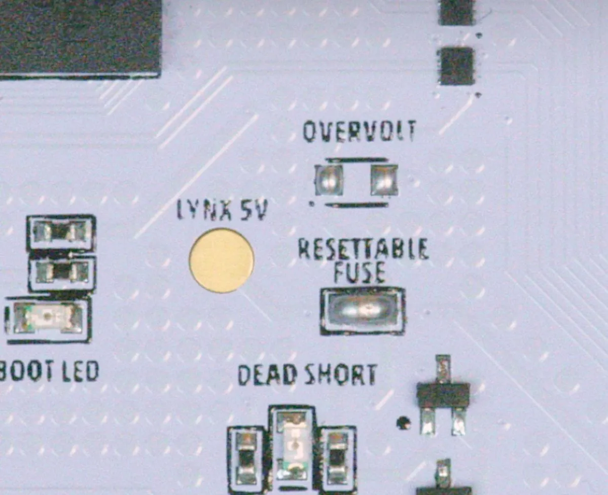
Section titled “Overvolt diode and fuse”Before connecting the LCD ribbon, it is best to remove the overvolt diode and bridge the fuse. The diode will overheat if the 5V rail goes slightly out of tolerance and doesn’t really protect much. The fuse can add inductor-like noise back into the circuit, so bridging it is recommended.
Wiring
Section titled “Wiring”Now connect the LCD ribbon to the board.
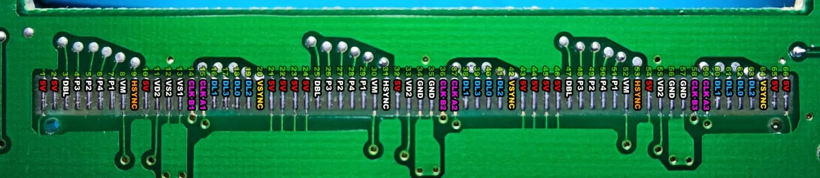
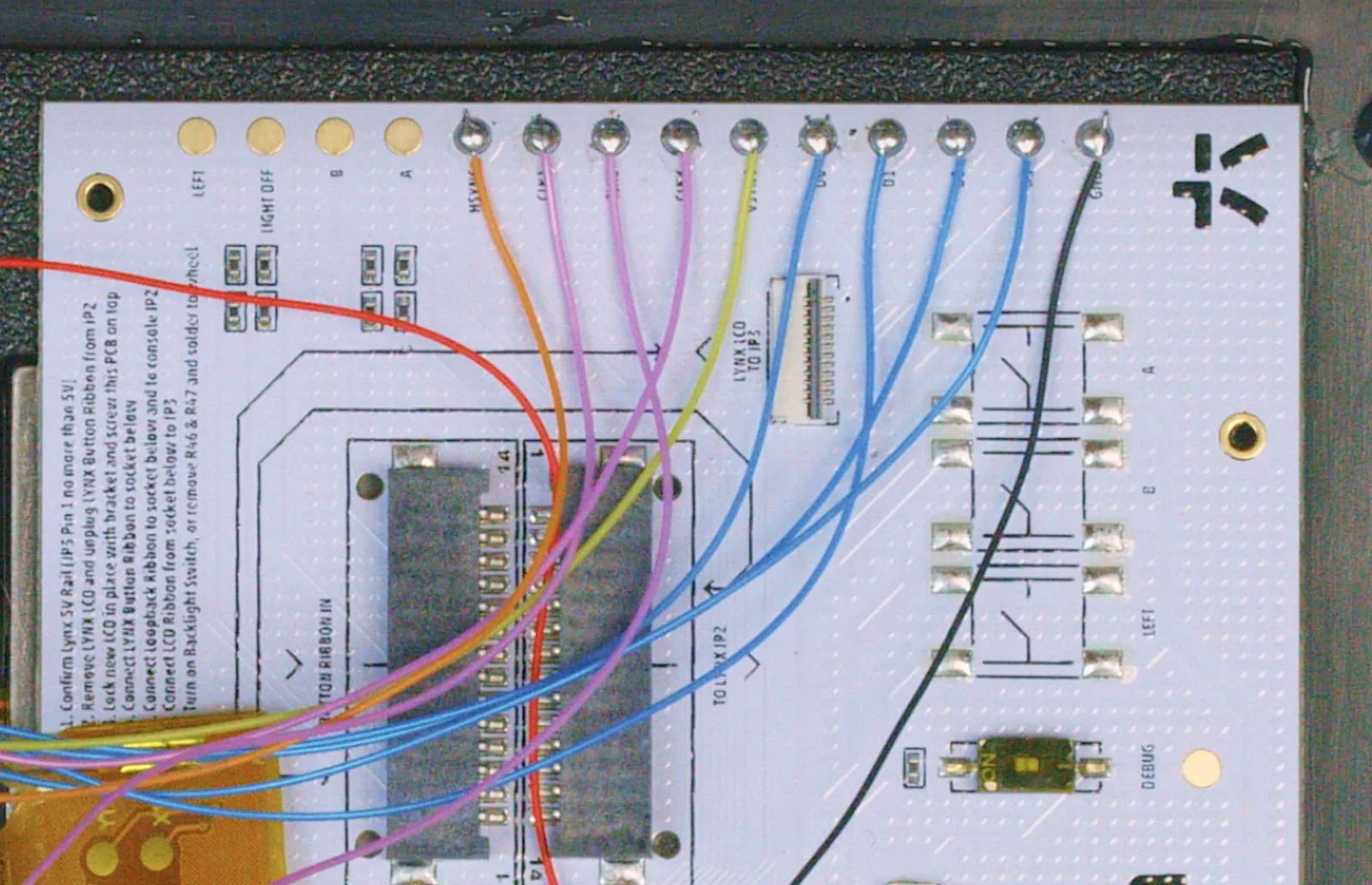
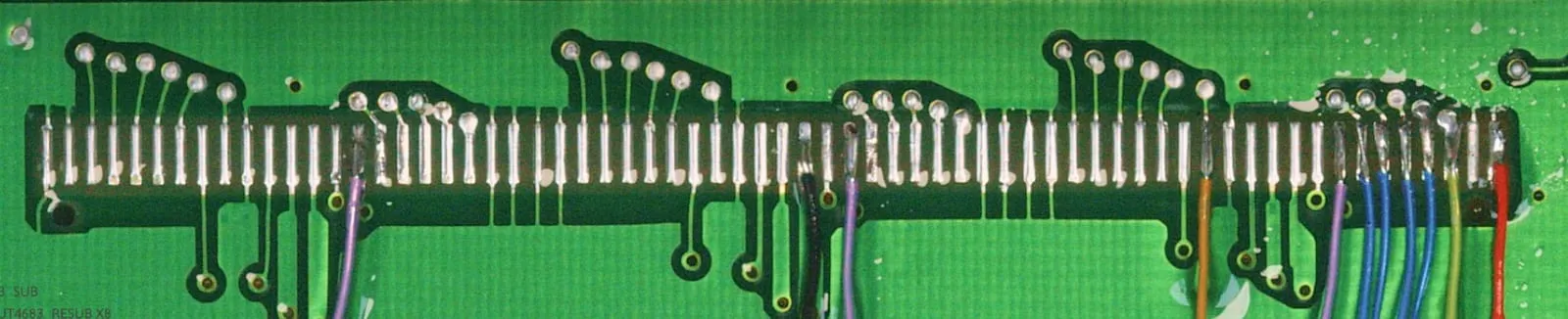
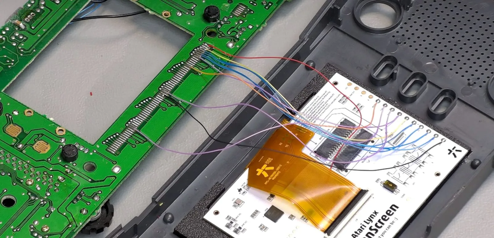
Next, hand wire every pin from the Lynx LCD ribbon to the connectors on the side of the board: ground, the data pins, the clock pins, H-sync and V-sync. Use the clock A signals, clock A1, A2 and A3. They repeat several times on the LCD connector.
The 5V connector on the Lynx CleanScreen sits underneath the LCD ribbon, so you have to disconnect the ribbon to solder the wire to the pad labelled “Lynx 5V”. In the install photos below it is the red wire coming out from under the LCD ribbon.
A and B solder points
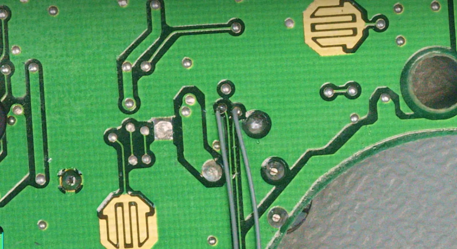
Section titled “A and B solder points”At the bottom right of the motherboard you will see the A and B buttons, with A on the outside. Follow the traces up above the speaker and you will see two vias: A is on the right, B is on the left.
Left solder point
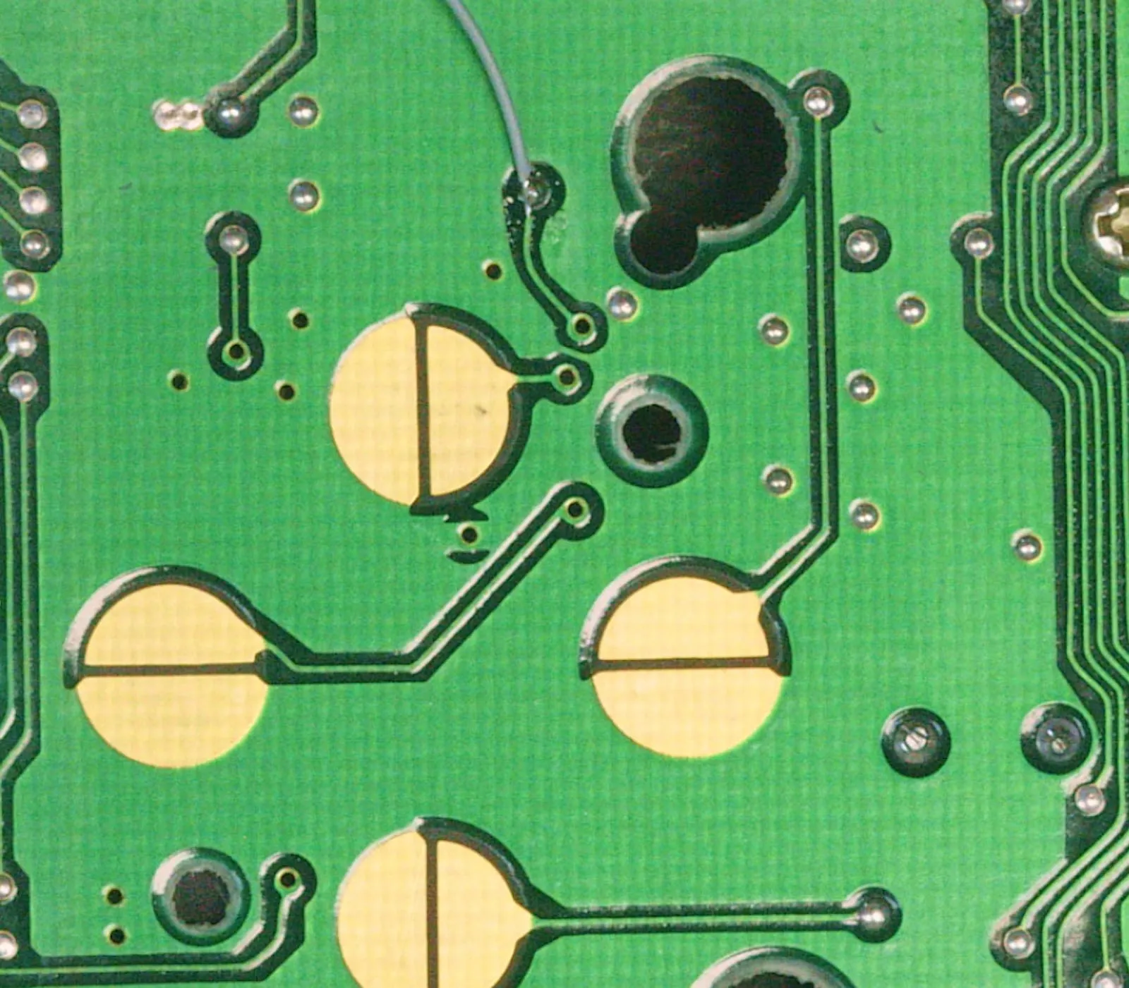
Section titled “Left solder point”For the left D-pad pad there is a via just above the up button that goes to the left pad. Check with a continuity test that this is correct on your revision. If not, follow the traces from the left pad through the board until you find a suitable spot.
Backlight
Section titled “Backlight”If you want adjustable brightness, remove the single screw on the contrast wheel, take off the plastic and remove resistors R34 and R59.
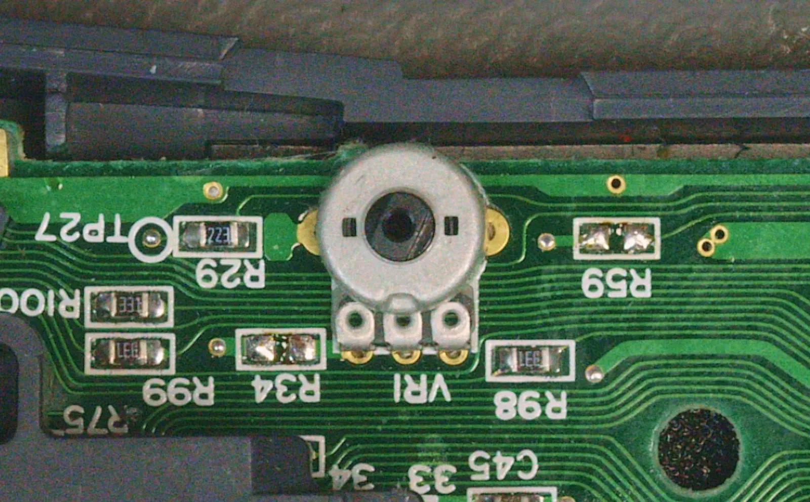
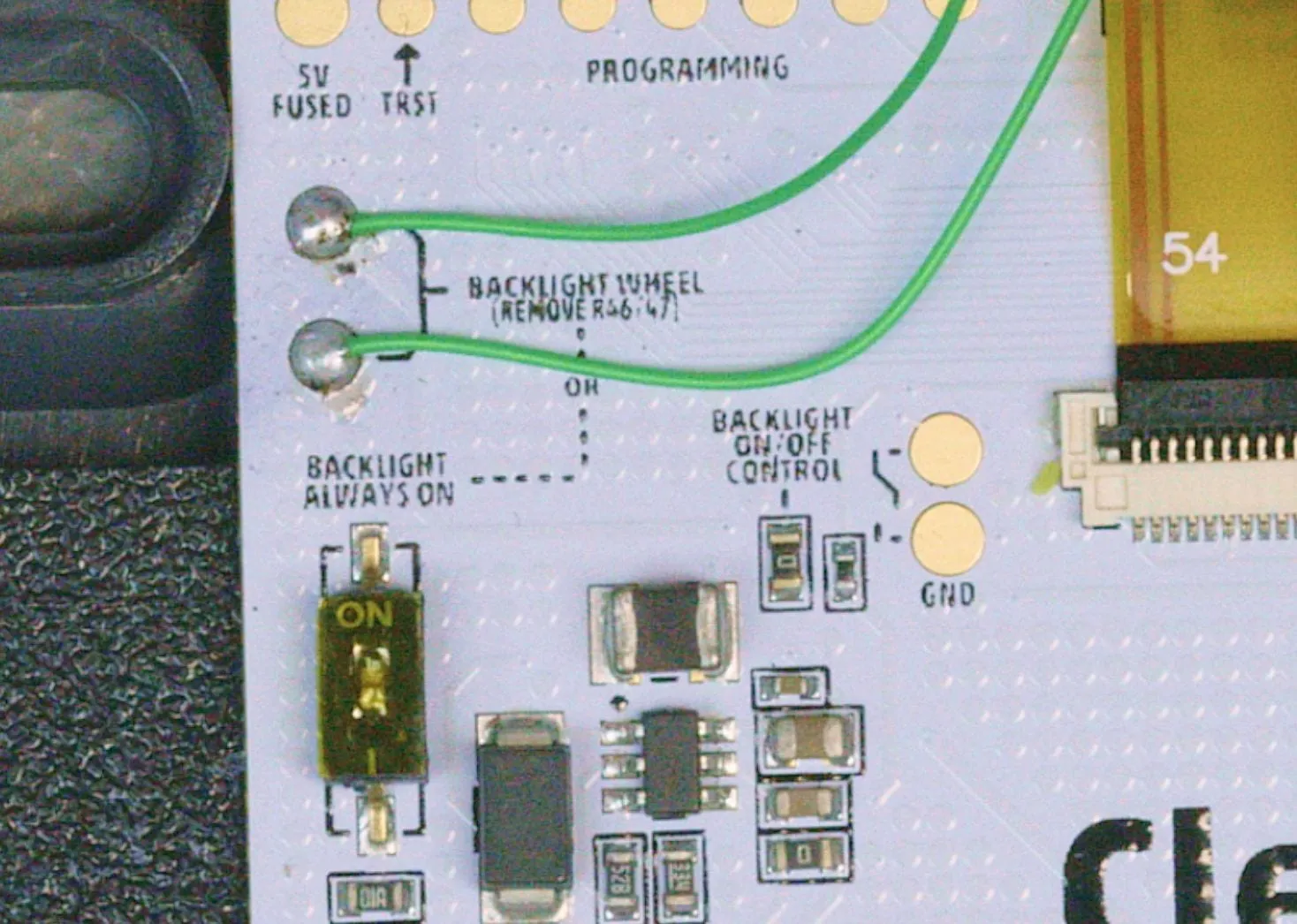
Then solder two wires to the opposite side of the board as shown in the image below and connect them to the backlight wheel pads on the CleanScreen.
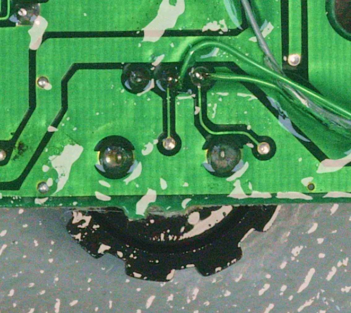
If you don’t want to wire up the wheel and are happy with a fixed brightness, flick the “backlight always on” test switch to the on position instead.
Finishing up
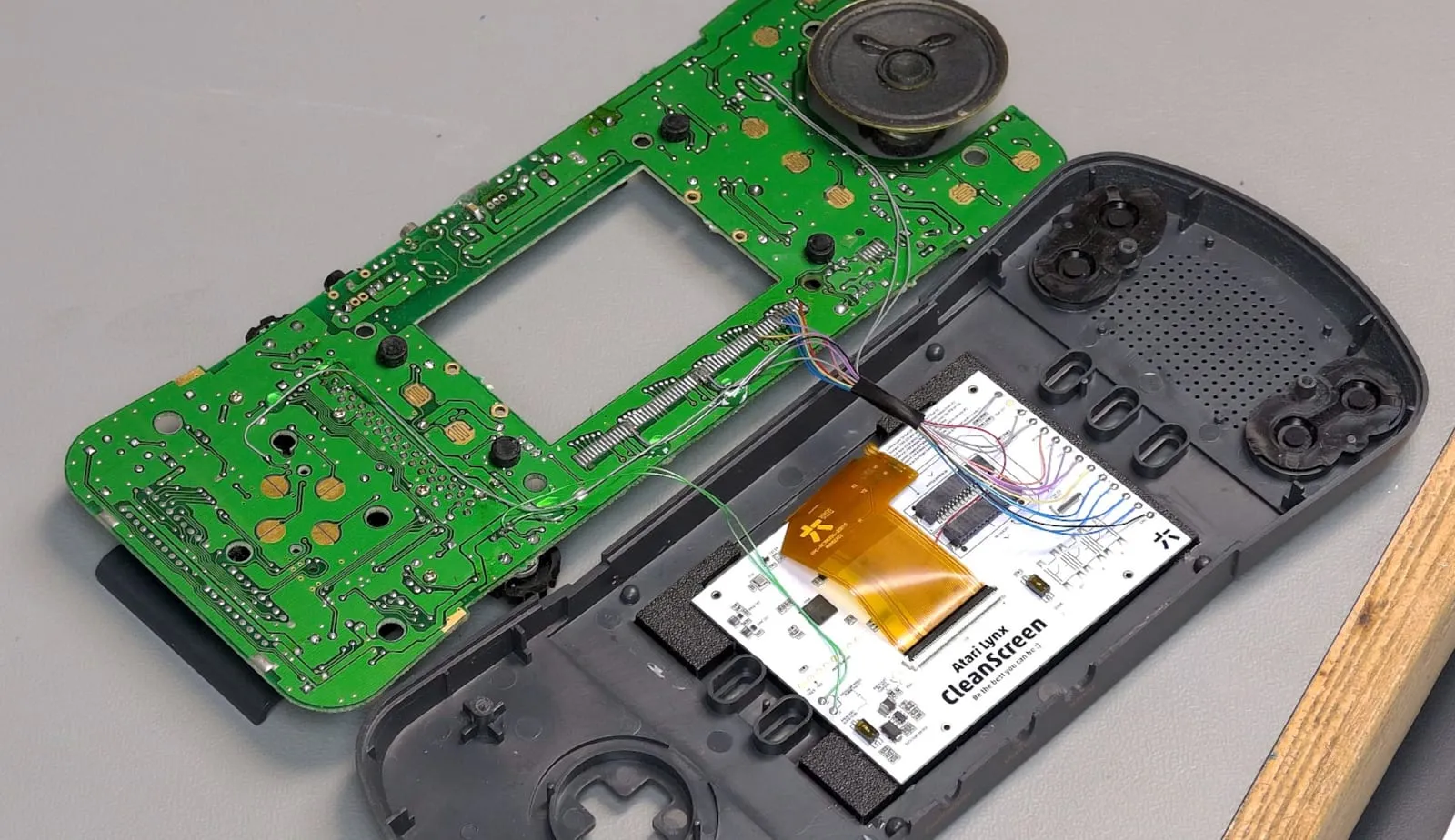
Section titled “Finishing up”Once you’re done you can tidy up the wires, or leave them as they are, it works either way.
Testing and on-screen menu
Section titled “Testing and on-screen menu”If everything is done correctly, the brightness wheel changes the backlight brightness (if you wired it up). Holding left, B and A for a few seconds brings up the on-screen menu.
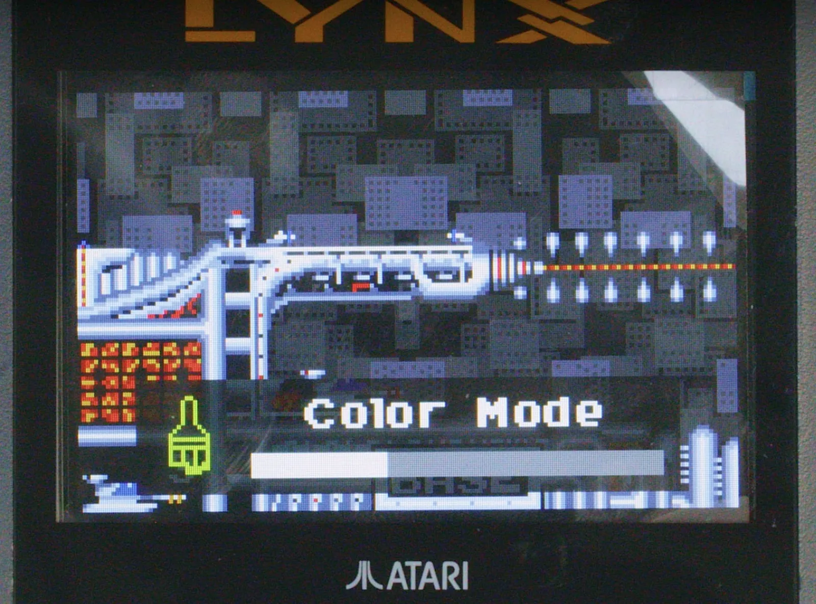
Navigate the menu with left and A, which act as left and right buttons, while B acts as a start button to enter and leave the menu. The menu offers colour modes, pixel grids, scanlines, VGA out and True Motion.