
[GBA] Hispeedido IPS V2 Kit
This guide covers the Hispeedido V2 GBA IPS kit and the FunnyPlaying V2 GBA IPS kit.
Video guide
Section titled “Video guide”Getting started
Section titled “Getting started”Required tools
Section titled “Required tools”- Soldering iron (optional, for brightness control)
- Tweezers
- J1 (Japanese Industrial Standard) screwdriver
- Y1 tri-point screwdriver
- IPS-ready GBA shell
- Kapton tape
- Double-sided gift tape (gentler adhesive that is easier to remove later)
Take inventory
Section titled “Take inventory”Make sure you have all the parts. According to Hand Held Legend, the kits include the following (see the product page for the current contents of our kit):
Before you proceed
Section titled “Before you proceed”- Fully disassemble your Game Boy Advance: Disassembly Guide (GBA Original) (Hand Held Legend)
- Find out whether you have a 32 pin or 40 pin GBA: GBA 32 pin or 40 pin?
- Fully dry test your kit before installation: How do I test the LCD
Install guide
Section titled “Install guide”Optional: tin all solder points
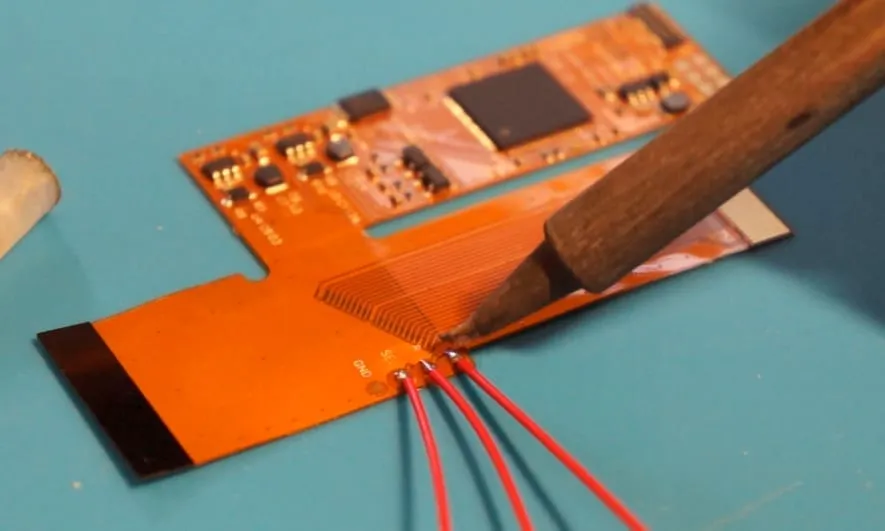
Section titled “Optional: tin all solder points”Add flux, then tin the connection points on the included ribbon cable. Solder the included wires to the connection points as shown. The GND connection is not required.
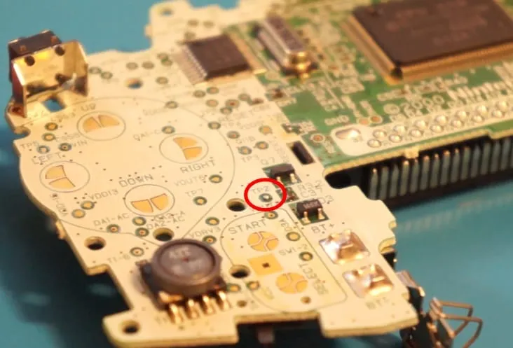
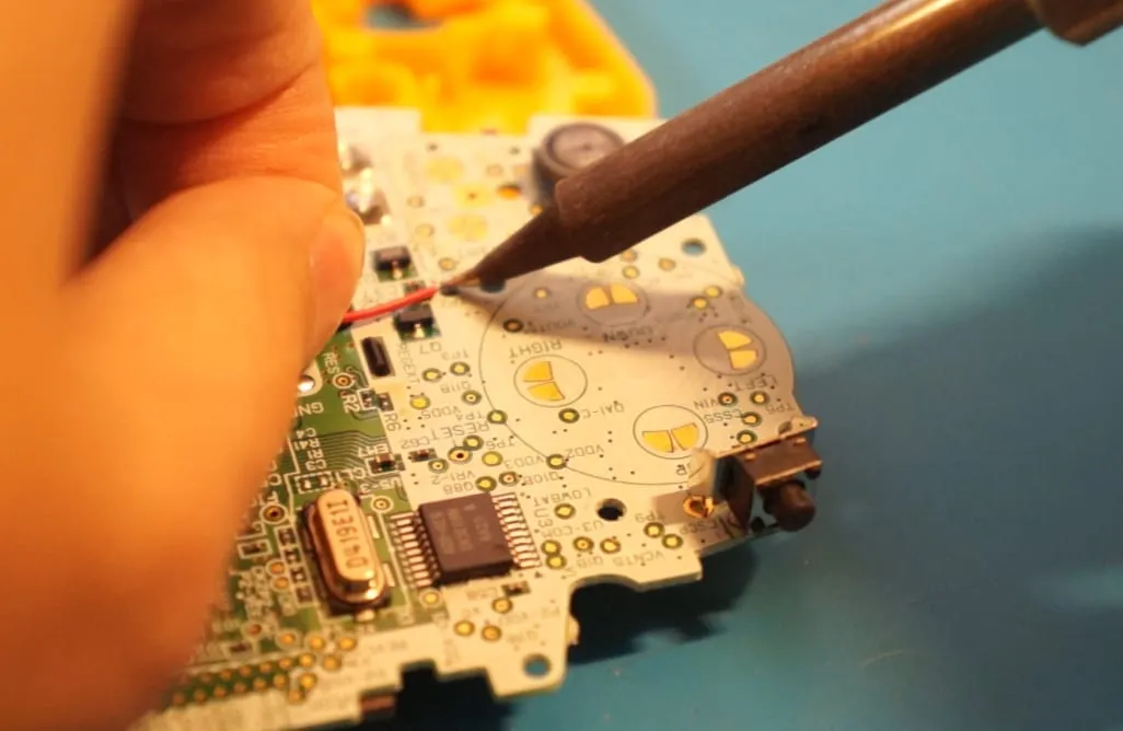
Add flux, then tin the pad labeled TP2 on the front of the main board. This will connect to the pad labeled “SEL” on the ribbon cable later on.
Display setup
Section titled “Display setup”Lay the IPS display and the included flex cable flat on your workspace. Connect the display to the flex cable. Take extra care here: the connector is very fragile!
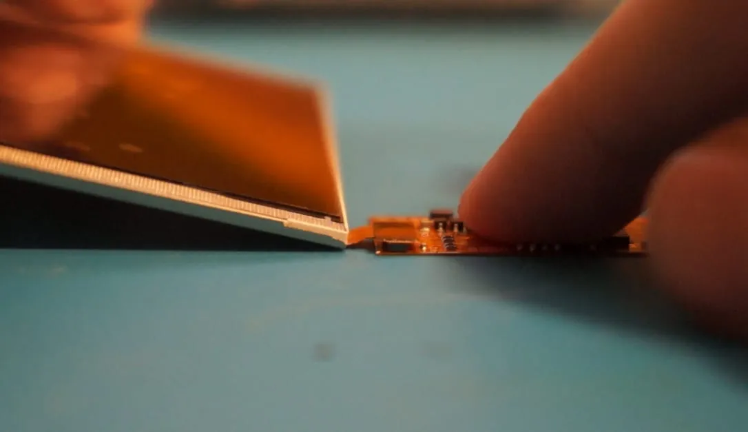
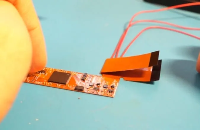
For 32 pin GBA consoles, bend the included flex cable as shown.
Flip the entire assembly over. Optionally add a small strip of double-sided tape to hold the ribbon cable against the back of the display.
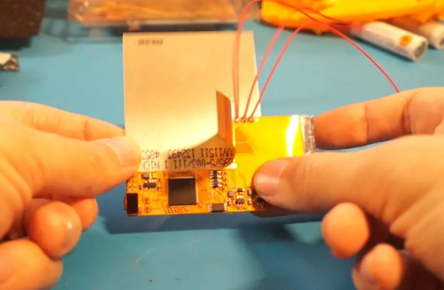
On 32 pin models, tuck the 40 pin connector away as shown:
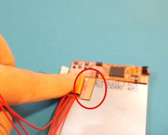
Insulate the screen
Section titled “Insulate the screen”Put a strip of Kapton tape over the unused connector.
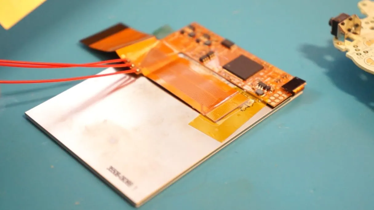
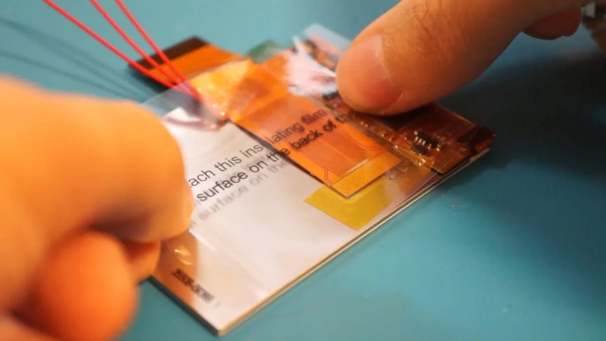
Stick the insulating film to the back of the LCD so it covers the flex PCB. If you’re using the FunnyPlaying kit, use several strips of Kapton tape to fully insulate the ribbon cable instead.
Start/Select area trim
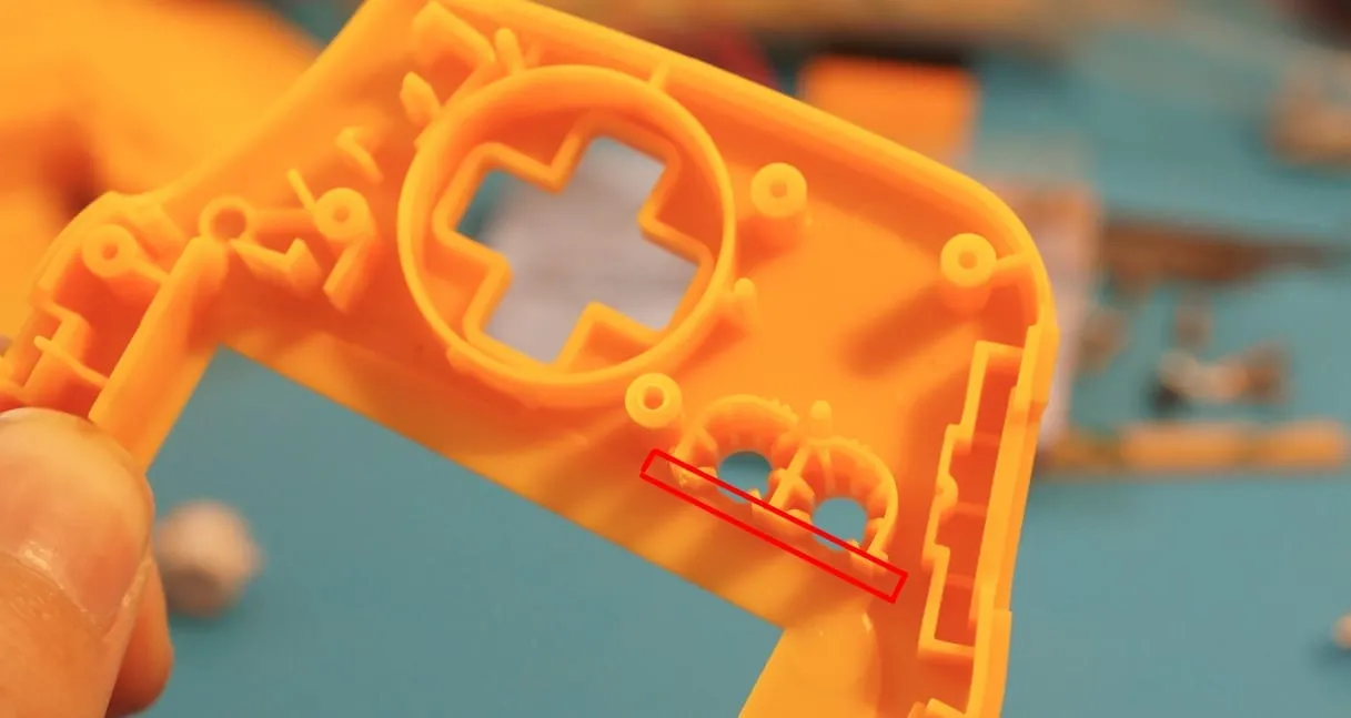
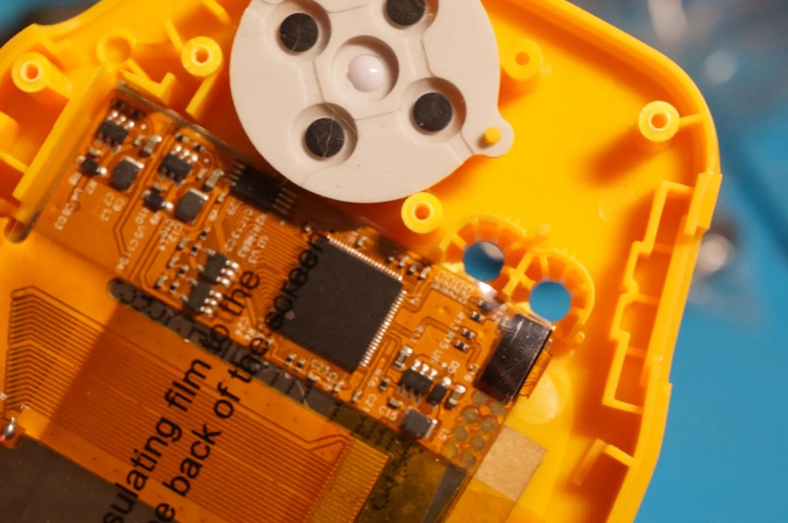
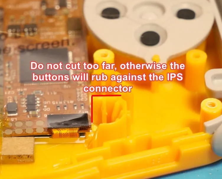
Section titled “Start/Select area trim”Even with pre-cut shells, we recommend carefully checking the Start/Select area and trimming as needed. The flex PCB extends past the IPS display by up to about a millimeter, and this can vary slightly.
The images below give an estimate of how much you’ll need to trim.
Screen adhesive and alignment
Section titled “Screen adhesive and alignment”Apply the screen adhesive to the inside of the shell as shown.
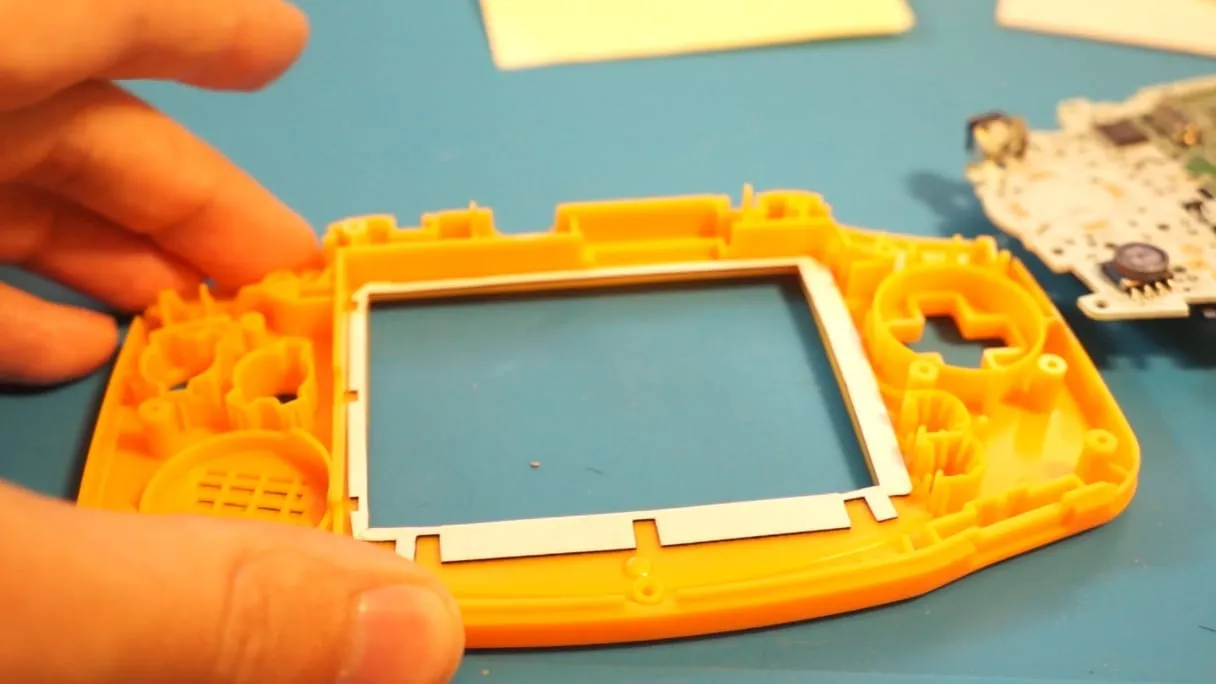
Remove the inner adhesive cover and the protective film from the IPS display. Install the alignment spacers together with the display. The IPS should sit flush against the right side of the housing, with the thinner alignment bracket on the left.
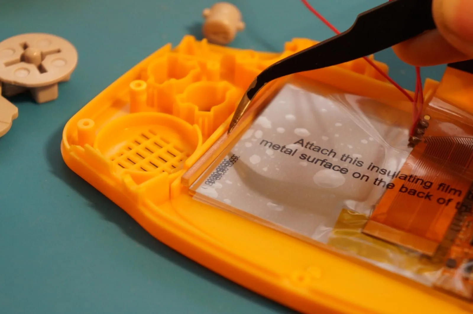
If you’re using a shell you trimmed yourself, you can also use the extra alignment bracket at the bottom of the screen.
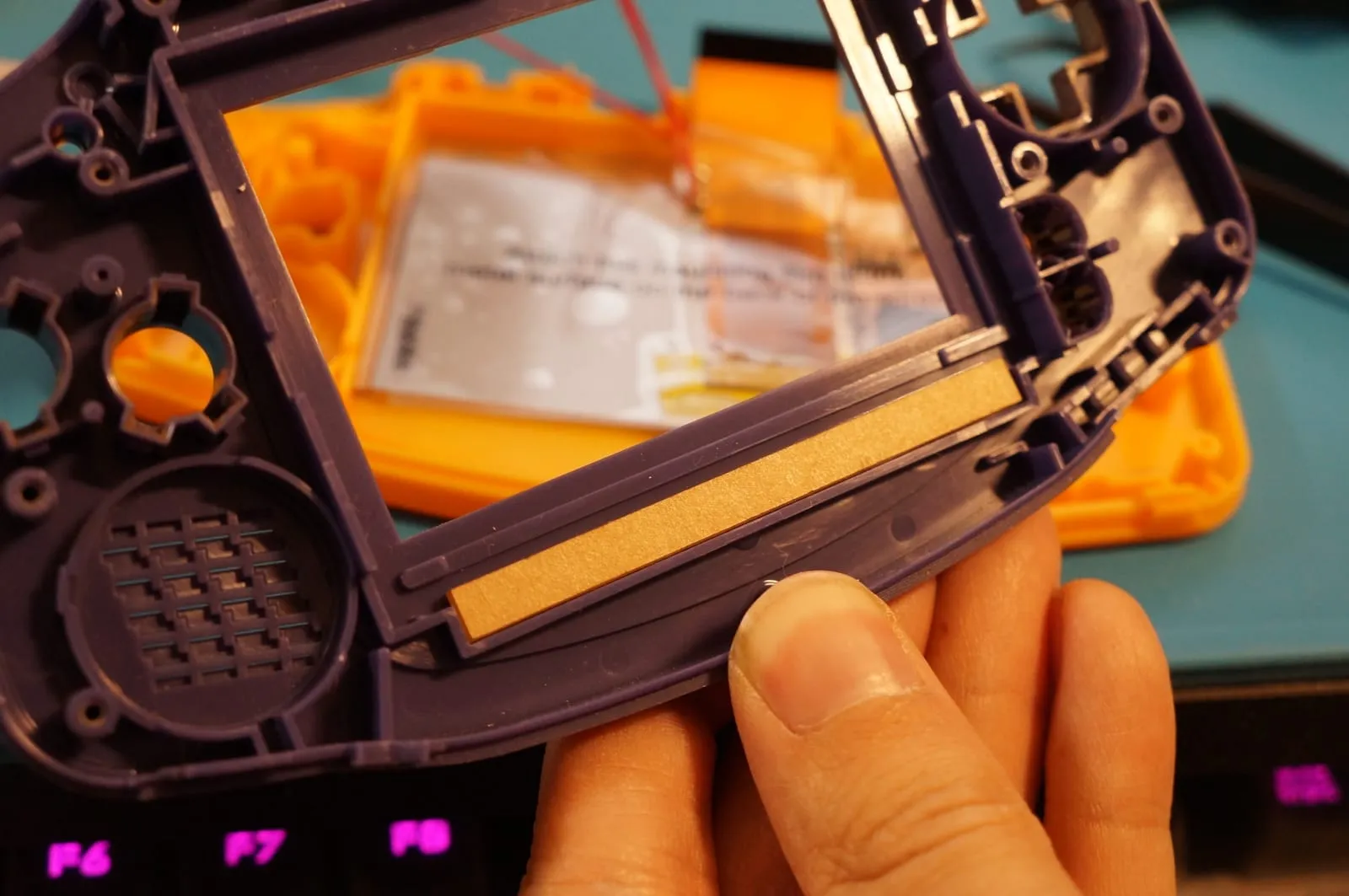
Main board placement
Section titled “Main board placement”Solder the Select wire to the TP2 pad you tinned earlier.
Place the insulation foam on top of the IPS display. Insert all face buttons, the LED lens and the button membranes.
Plug the display ribbon cable into the connector as shown. This is easier while the main board isn’t screwed down yet and keeps the cable from being bent too sharply.
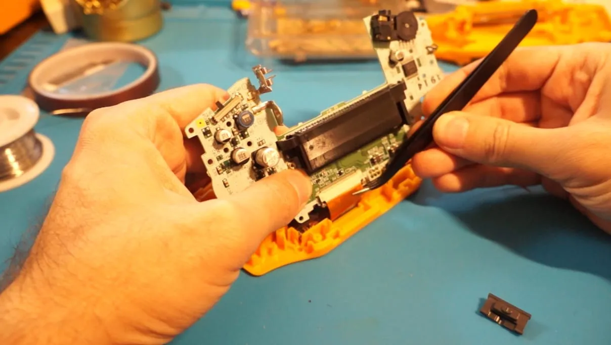
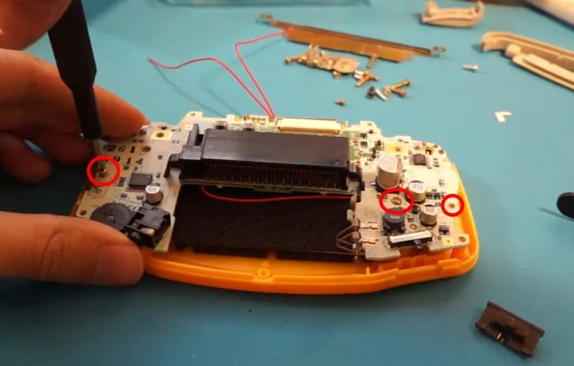
Replace the three screws that hold the main board to the front shell.
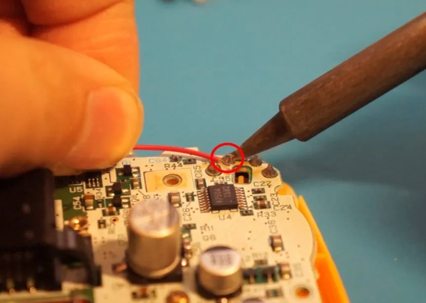
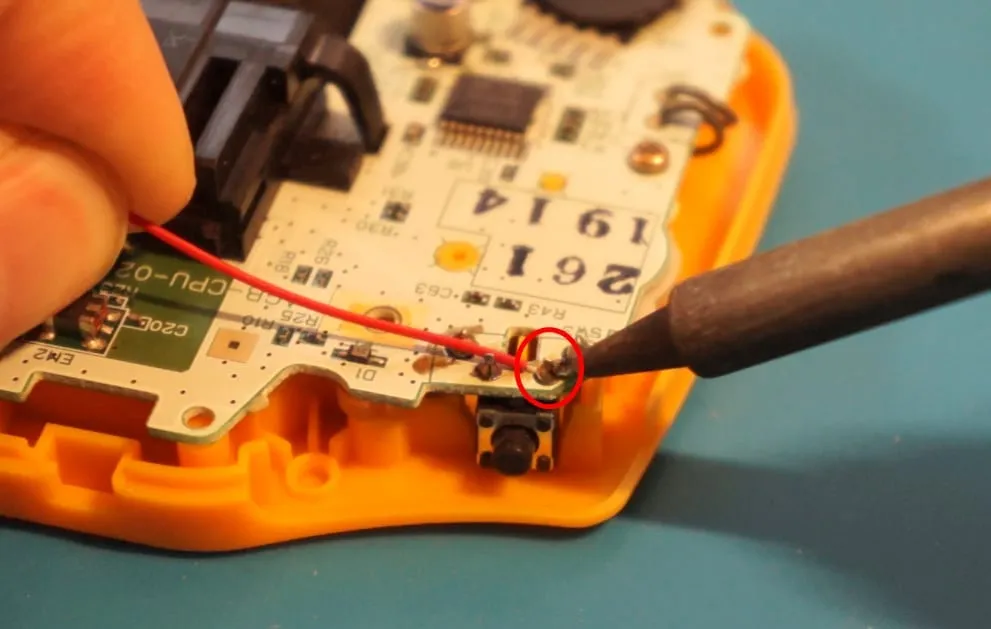
Solder the L and R button wires as shown.
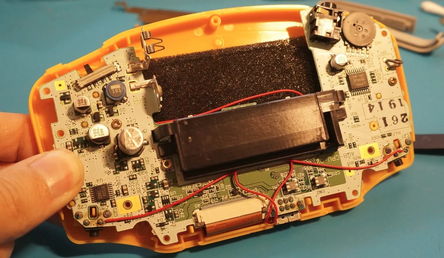
Route the wires as shown so they don’t get pinched during reassembly.
Test and reassemble
Section titled “Test and reassemble”Install the power switch, shoulder buttons and rear shell. Don’t screw anything together yet. Insert batteries and power the console on. The display should light up. If it doesn’t work as expected, carefully inspect all connections and try again.
If you did the optional soldering steps, you can adjust the brightness by holding Select and pressing L or R.
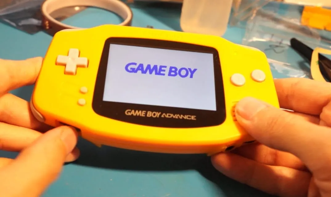
If everything works as expected, finish by replacing the rear screws. See the Disassembly Guide (GBA Original) if you need help.
Troubleshooting
Section titled “Troubleshooting”- IPS Troubleshooting (Hand Held Legend)