[GG] RetroSix CleanScreen V2/V3
CleanScreen V3
Section titled “CleanScreen V3”You can identify the V3.0 by the 4 switches on the top left, including the Screen Test switch.
A written guide is available from RetroSix.
Installation
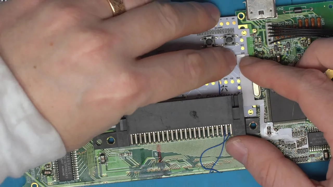
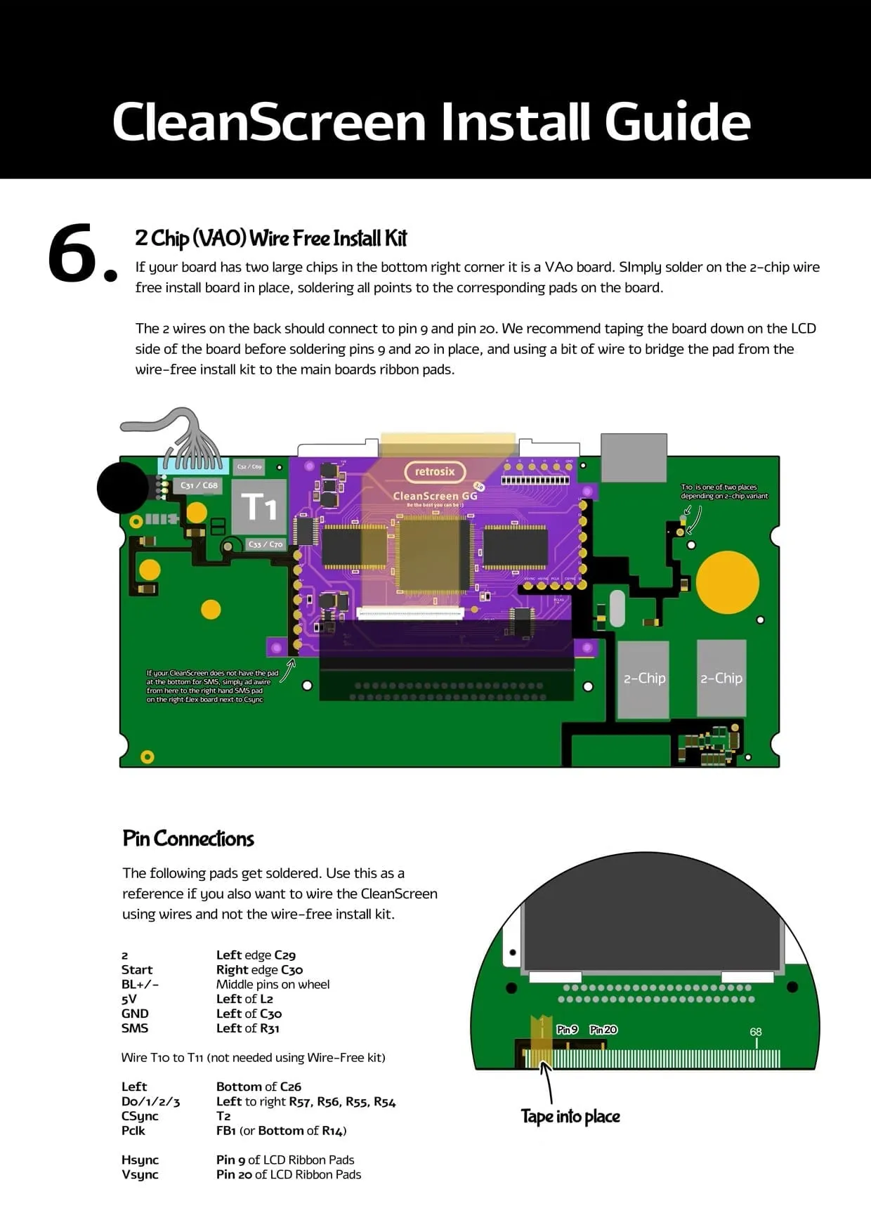
Section titled “Installation”Install the flex ribbon as usual and connect both sides of the ribbon. What’s new is that the V3 goes back to HSync and VSync, like the V2. The kit includes two wires for this:
- HSync to LCD pin 9
- VSync to LCD pin 20
▶ Watch in the video from 0:50
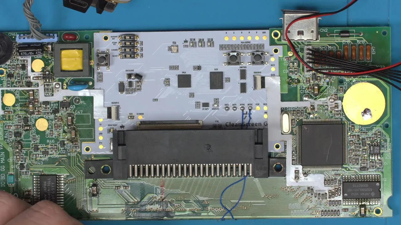
The two pins that used to set the colour modes are now DAT4 and DAT5. On this version they act as colour mode pins and must be soldered to ground (GND) or 5V. That gives you four colour modes:
| DAT4 | DAT5 | |
|---|---|---|
| GND | GND | Default, works on most consoles |
| 5V | GND | |
| GND | 5V | |
| 5V | 5V |
On about 90% of boards you simply tie DAT4 and DAT5 to any ground pad. If the colours are off (for example too red or too green), try the other combinations, such as DAT5 to GND and DAT4 to 5V. RetroSix asks for feedback (for example on Discord) if you need to change the colour mode.
▶ Watch in the video from 1:40
Clock booster
Section titled “Clock booster”The clock booster comes free with the CleanScreen. It stabilises the pixel clock (PCLK) and turns a weak clock into a clean full 5V signal with sharp edges. Otherwise, irregularities in the Game Gear clock can cause glitches such as jittering horizontal lines. RetroSix recommends the clock booster for every board; the V3.1 has it built in.
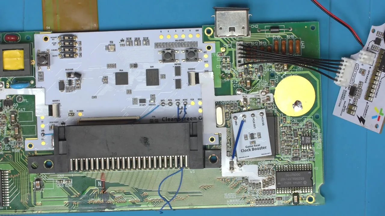
Instead of connecting the Game Gear clock straight to the ribbon, you route it into the clock booster and from there to the CleanScreen:
- Place the clock booster wherever suits you and keep it flat with double-sided tape.
- Connect 5V and GND to any pads. On the single ASIC (1-chip) version, the short blue wire reaches the 5V pad nearby; you can also use the 5V side of the caps.
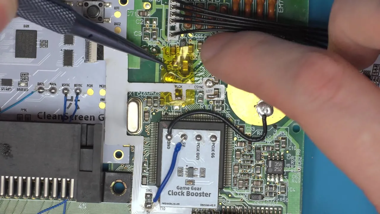
- Lift the ribbon’s PCLK pin so it is no longer soldered. Slide some Kapton tape underneath, fold it back over and stick it down so the pin definitely can’t make contact.
- Connect PCLK Out on the clock booster to the PCLK pad. You could use the flex ribbon for this, but RetroSix prefers the pad on the CleanScreen PCB so the ribbon pad doesn’t rip off.
- Finally, connect the original Game Gear PCLK pad (where the ribbon would have been soldered) to PCLK GG on the clock booster.
▶ Watch in the video from 2:20
▶ Watch in the video from 3:46
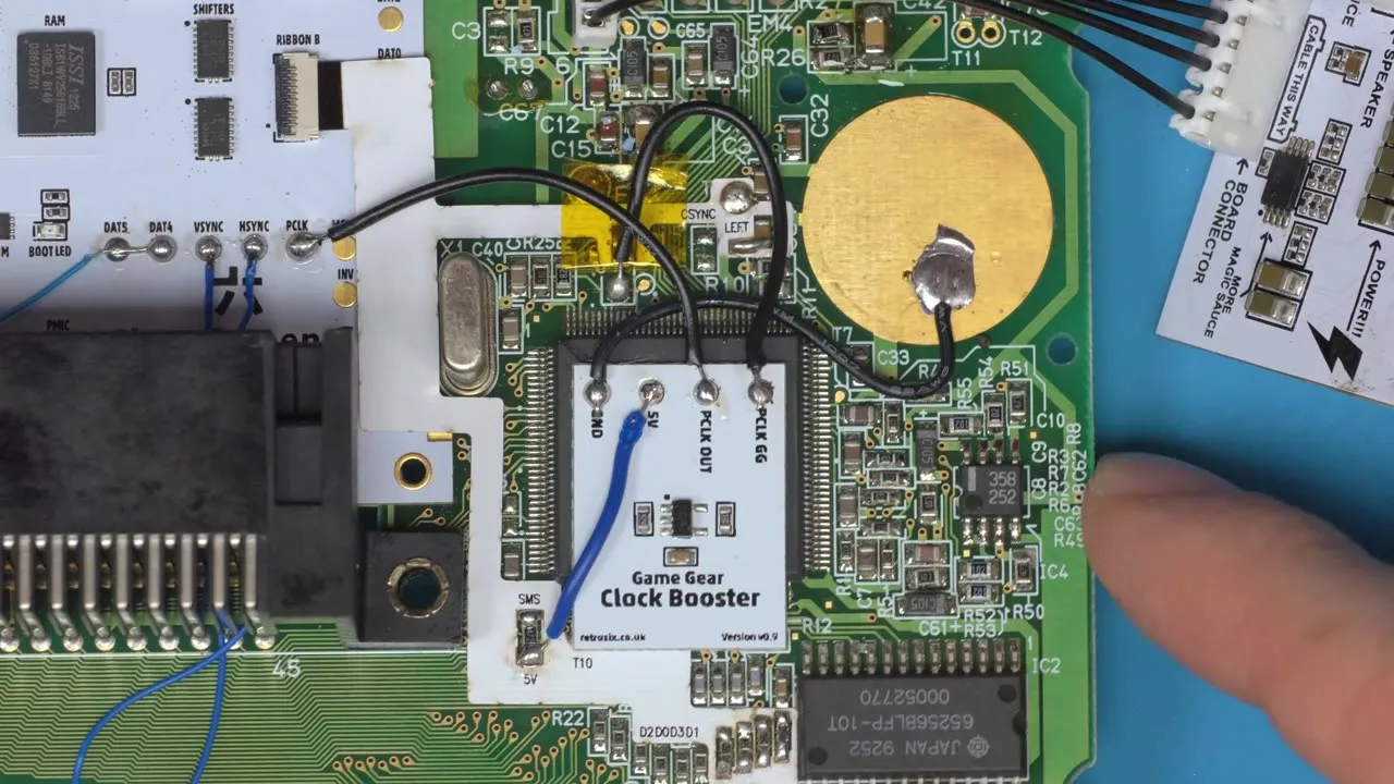
▶ Watch in the video from 4:36
Switches and diagnostics
Section titled “Switches and diagnostics”The V3 has several new switches and indicators that help with troubleshooting.
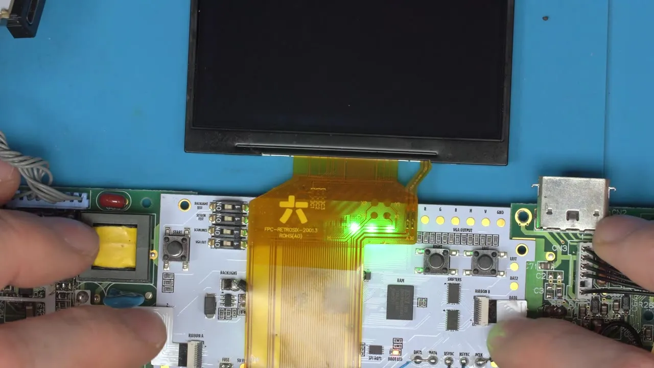
▶ Watch in the video from 8:44
Backlight test: Always turns the backlight on, even if the brightness wheel is turned down or not wired up yet. This lets you test without wiring the wheel.
Screen test: This test doesn’t need a working Game Gear. Applying 5V and GND to the CleanScreen is enough. This way you can find out whether the console or the CleanScreen is at fault. It’s best to turn on the backlight test as well. You’ll then see a coloured border, and the colour in the middle shows live which signals are missing:
| Colour in the middle | Meaning |
|---|---|
| Black | Everything OK |
| Green | VSync missing |
| Blue | HSync missing |
| Red | PCLK missing (no clock) |
| Purple | HSync and PCLK missing |
| Cyan | VSync and HSync missing |
| White | All three missing |
If several signals are missing, the colours mix accordingly.
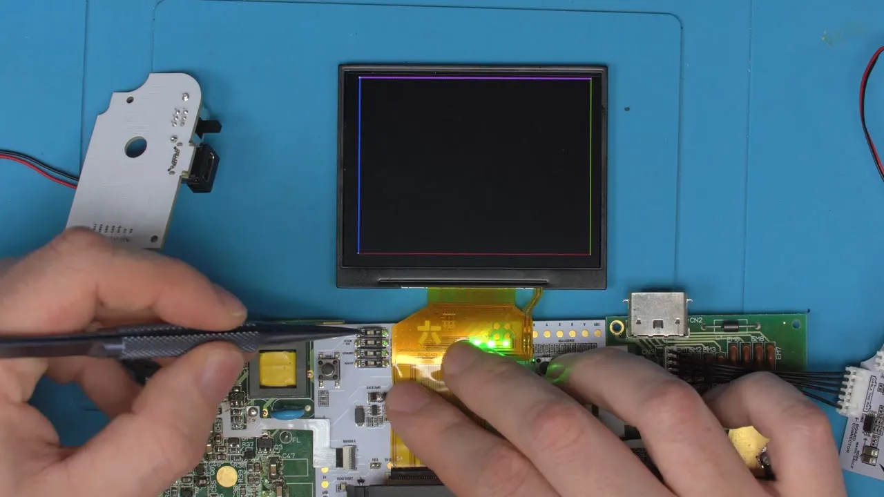
▶ Watch in the video from 9:40
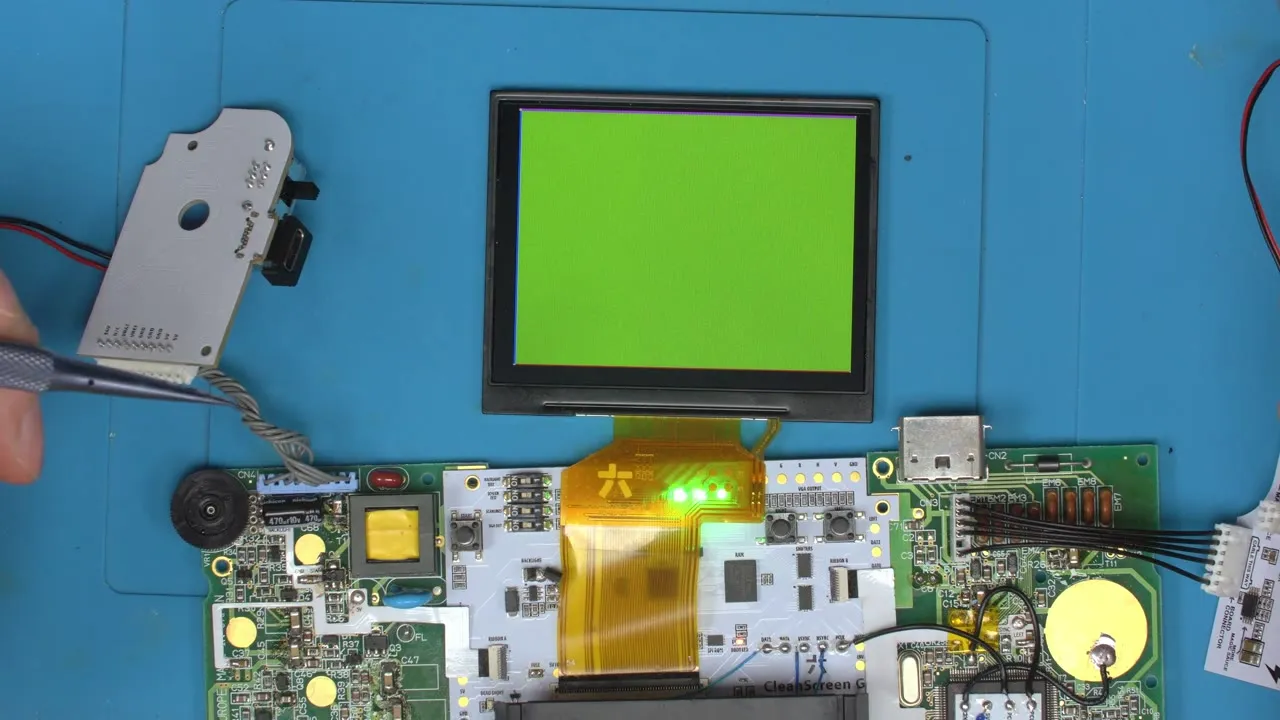
▶ Watch in the video from 10:03
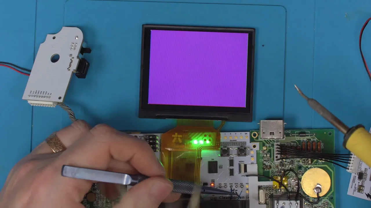
▶ Watch in the video from 10:33
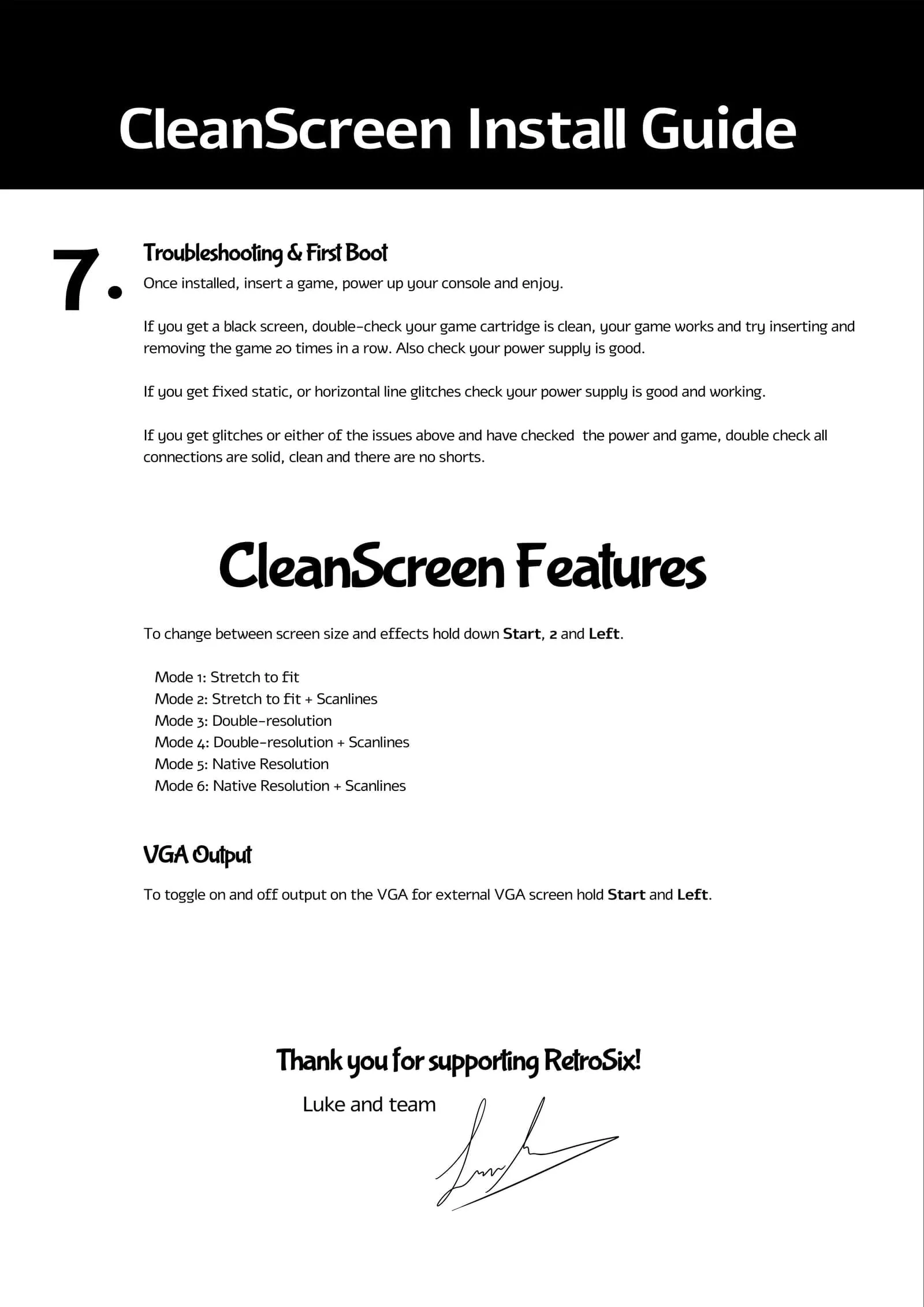
Debug mode via buttons: If the console is fully assembled, turn it on and hold Start + 2 + Left (the menu combination) for about 5 seconds. Debug mode then opens for as long as you hold the buttons and turns off again when you let go. If you don’t see a debug window after 5 seconds, either the brightness wheel is bad (if the backlight test is off) or something is wrong with the CleanScreen.
LEDs: Indicators for the 5V input, 3.3V and 1.2V, plus a boot LED that shows the CleanScreen code is running.
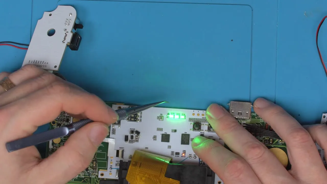
▶ Watch in the video from 12:09
Scanlines: Permanently turns on the vertical scanlines (the classic Game Gear scanlines). You can also do this in the menu, for example with Pixel Grid, but the menu doesn’t save settings because the FPGA doesn’t have enough memory for it.
VGA out: Permanently enables VGA output mode, for example for a consolised Game Gear. This is also available in the menu, but again it isn’t saved.
Install video
Section titled “Install video”Identifying 1-chip vs 2-chip
Section titled “Identifying 1-chip vs 2-chip”1 chip:
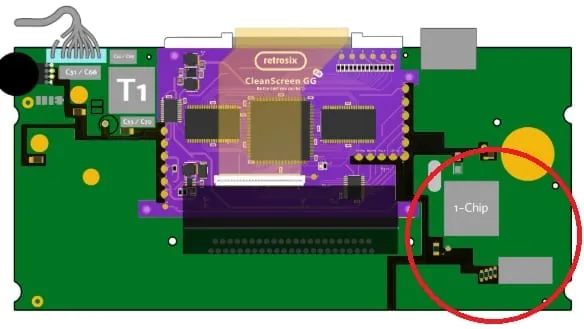
2 chip:
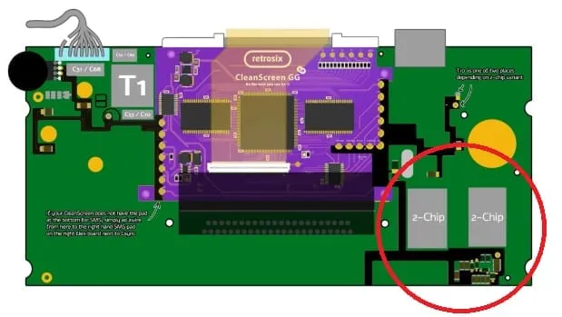
CleanScreen V2
Section titled “CleanScreen V2”Hold Start + 2 + Left to open the menu. Left and 2 move left and right in the menu, Start goes in and out of a menu.
Installation
Section titled “Installation”This guide is for the V2 version of the CleanScreen PCB and flex cables. V1 boards are installed the same way, except you no longer need to solder HSYNC or VSYNC; instead you also need to tie DAT4 to ground if you use the (latest) RetroSix IPS LCD, or to 5V if you use a TFT LCD.
Tie DAT5 to ground by default. If you get color issues that toggling the 1CHIP/2CHIP switch doesn’t fix, tie DAT5 to 5V instead (see this video from RetroSix).
Written guide for V2/V3 flex cables and V2 PCB
Section titled “Written guide for V2/V3 flex cables and V2 PCB”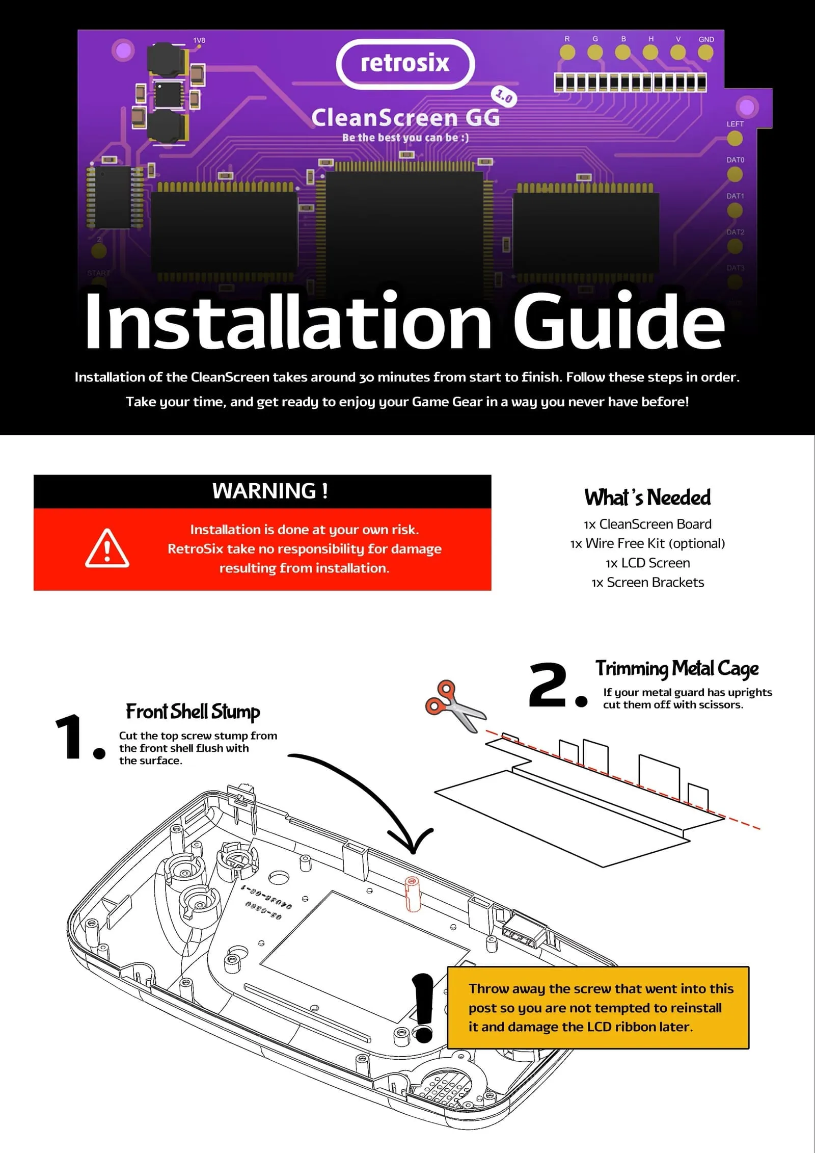
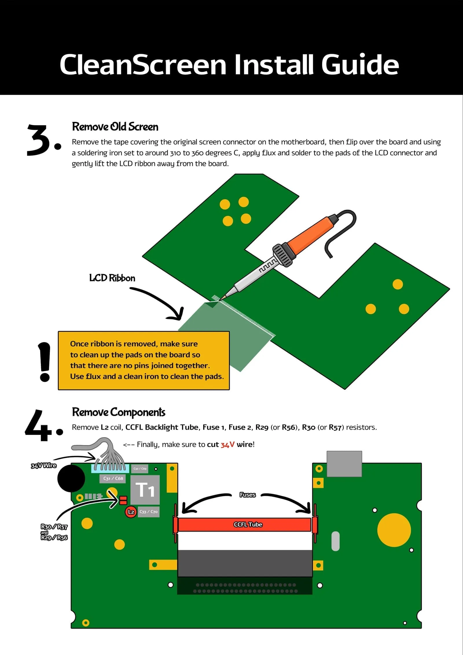
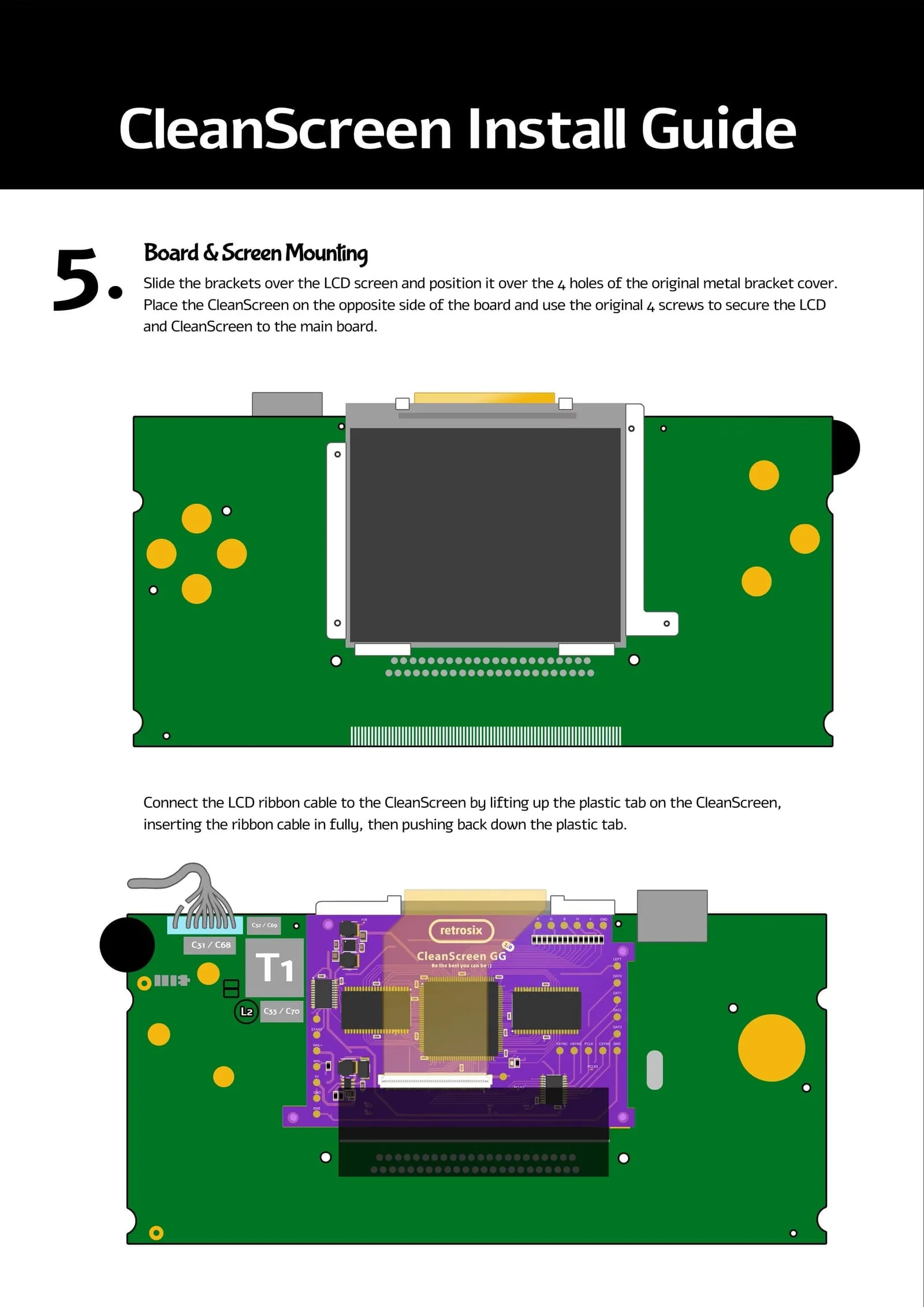
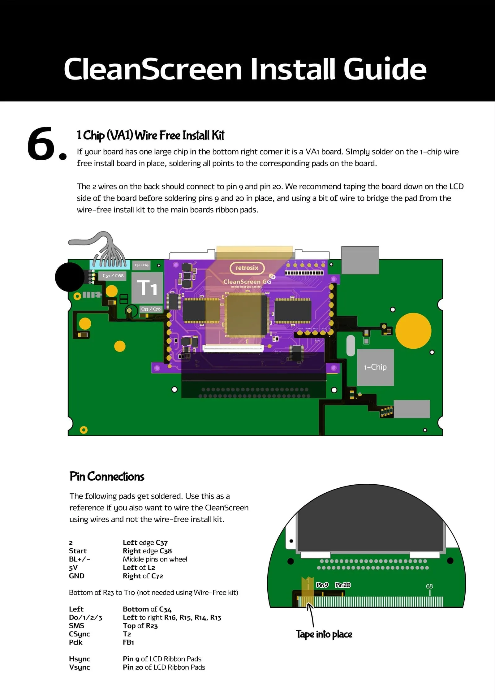
LCD cable issues
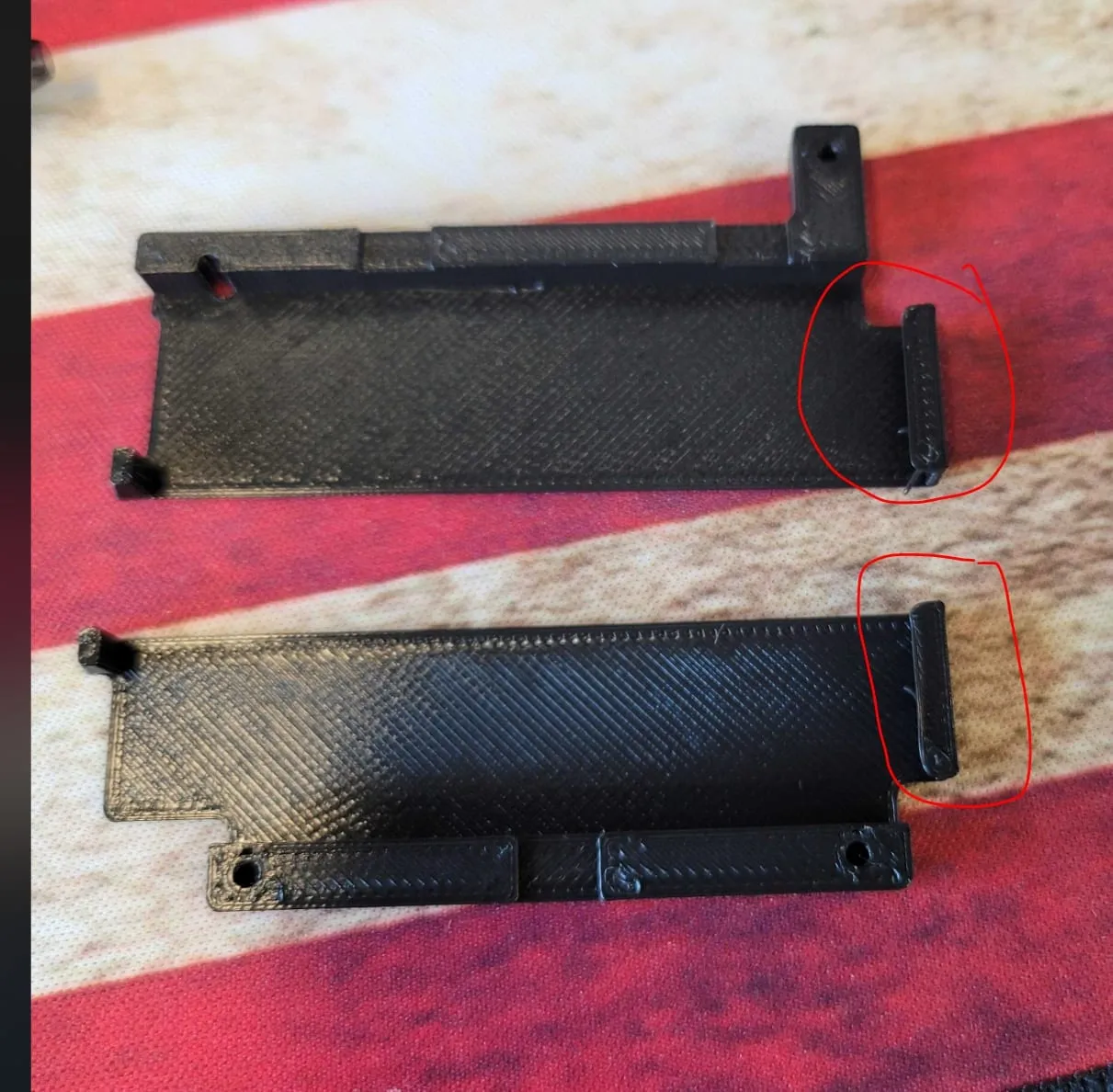
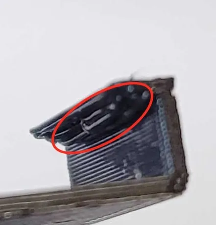
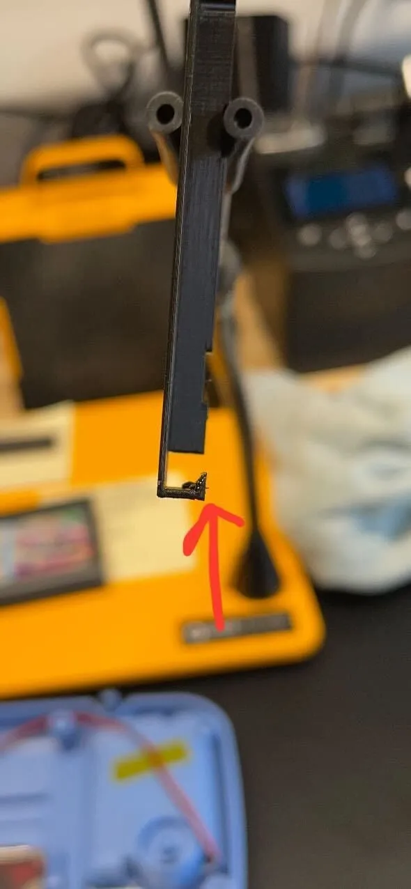
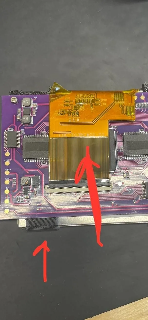
Section titled “LCD cable issues”The CleanScreen cable doesn’t have enough lead, sits crooked or generally doesn’t fit well enough for a good connection.
Solution
Section titled “Solution”The 3D printing process can leave extra material in the hooks of the brackets. This extra plastic pushes the cable away from the connector. Simply remove these bits of plastic so the LCD sits flush with the brackets and the CleanScreen can be installed properly.