
Replacing Capacitors (Recap) and Diagnostics
This is a general reference guide for replacing surface mount (SMD) and through-hole electrolytic capacitors. Be careful when working with electrolytic capacitors: too much heat can make them explode. Always wear eye protection and hand protection when doing this kind of work!
To find out whether your console needs a recap in the first place, you can check it with a multimeter, see Diagnostics: measuring capacitors.
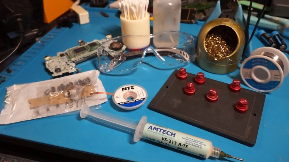
Required tools
Section titled “Required tools”- Temperature controlled soldering iron
- PCB holder
- Nitrile work gloves
- Eye protection
- Brass sponge
- Leaded solder
- Solder flux (paste or gel)
- Solder wick/braid
- 99% isopropyl alcohol
- Cotton swabs
- Fume extractor or open window
- Flush cutters
- Tweezers
Getting started
Section titled “Getting started”This guide assumes you are comfortable with soldering. If you are just starting out, check out Hand Held Legend’s introductory guide first: Soldering Iron Guide
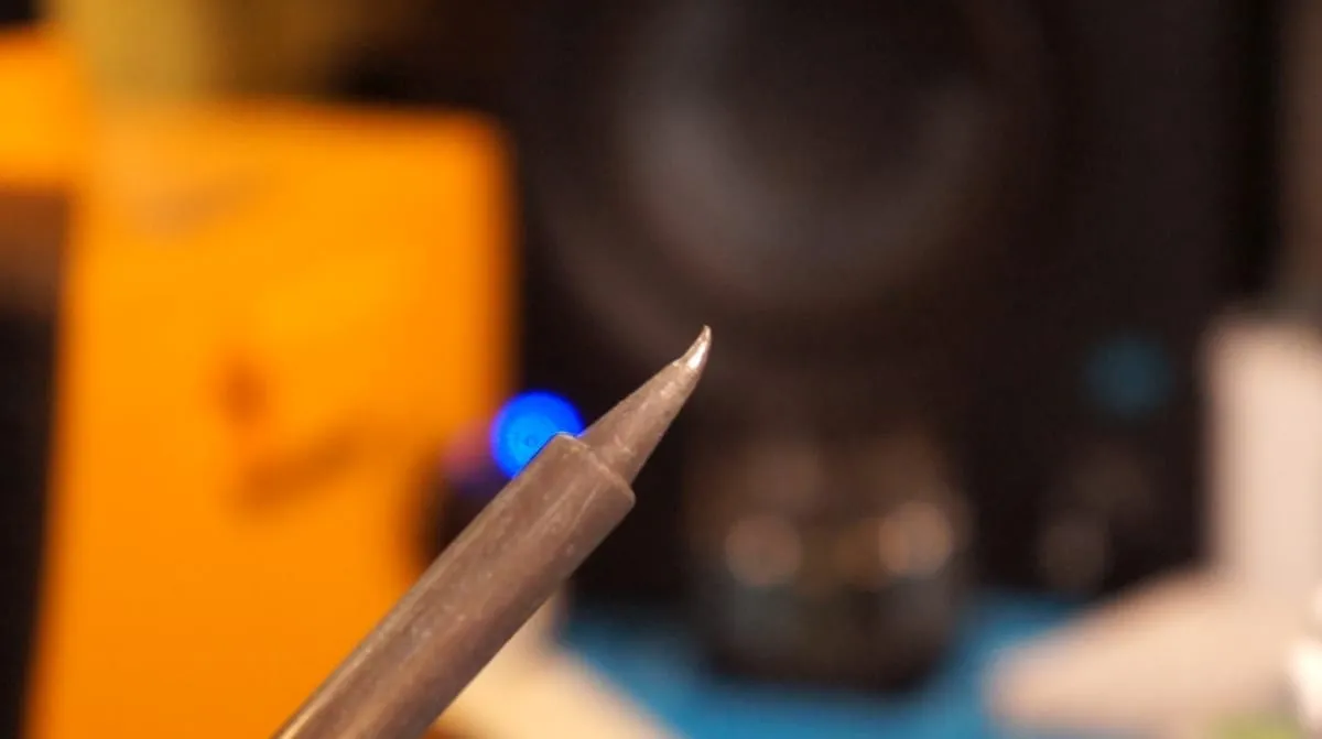
A curved soldering tip is used here. With practice and by trying different tips, you’ll likely develop your own preference.
Note the existing placement
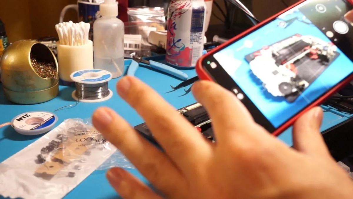
Section titled “Note the existing placement”Before you start, take a picture of the existing capacitor placement. When you are replacing many capacitors, it helps you remember which cap goes where and which value each one should have.
As a rule of thumb, replacement capacitors should match or slightly exceed the original capacitance (marked in µF, microfarads) and match or exceed the original voltage rating. For example, a 200 µF 12 V capacitor can be replaced with a 220 µF 24 V capacitor in most cases.
Tin the existing connections
Section titled “Tin the existing connections”Add flux to both exposed connections on either side of the capacitor. If you are removing a through-hole capacitor, do this on the capacitor’s solder joints on the underside of the board.
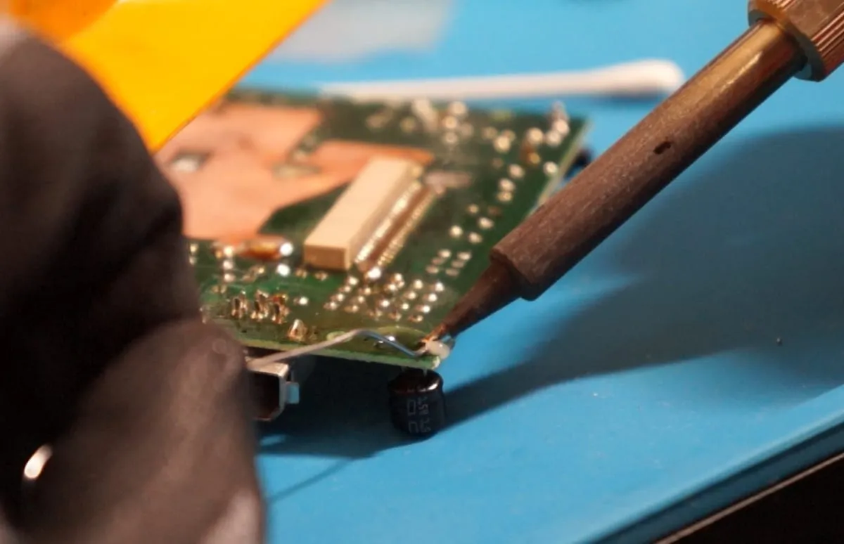
Use your soldering iron to add leaded solder to each capacitor leg/connection. The leaded solder mixes with the original lead-free solder and lowers its melting point. This makes removal easier and reduces the risk of ripped pads or burn marks.
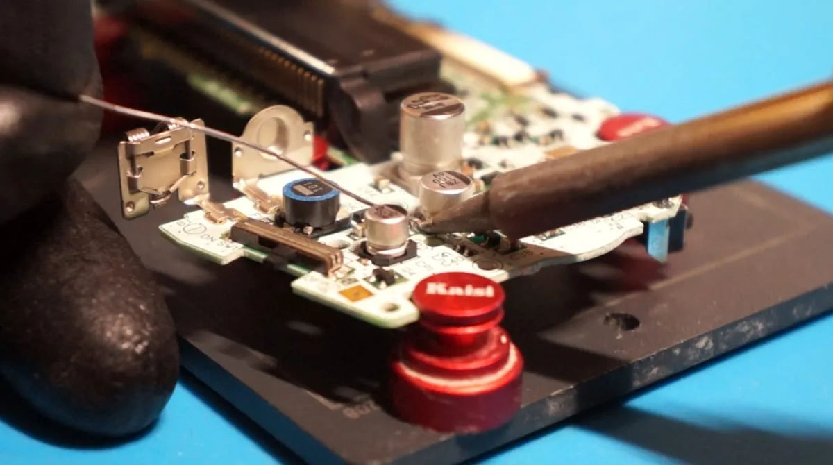
For surface mount capacitors continue with section A, for through-hole capacitors with section B.
A) Surface mount capacitors
Section titled “A) Surface mount capacitors”Heat and lift
Section titled “Heat and lift”Heat one leg of the capacitor and gently lift it. The goal is not to pull the capacitor off, just to raise the leg off the board. It may not be completely desoldered at this point, which is okay!
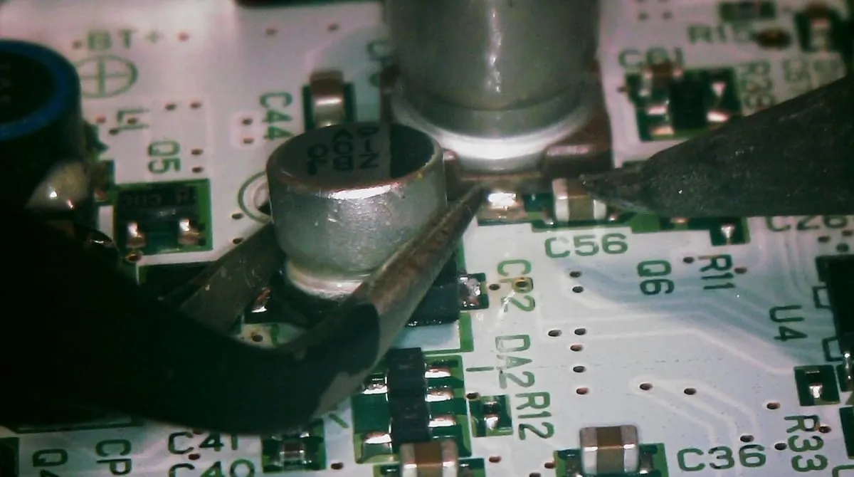
Repeat the same step on the other leg. Keep going back and forth until the capacitor is fully removed.
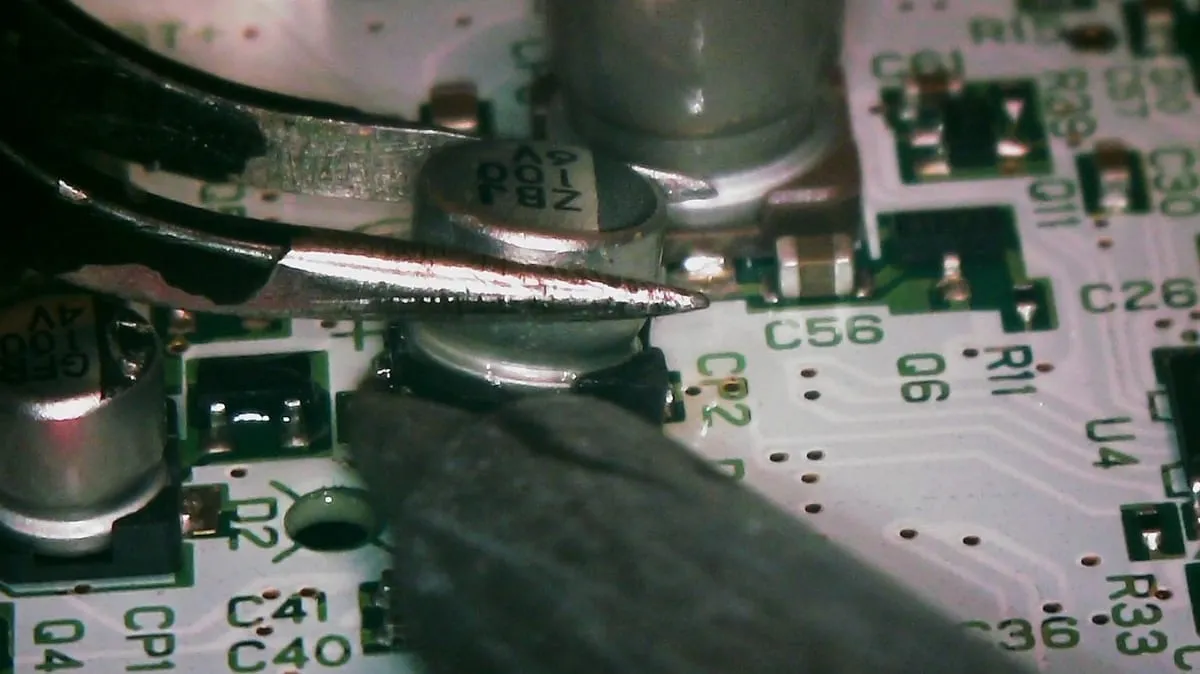
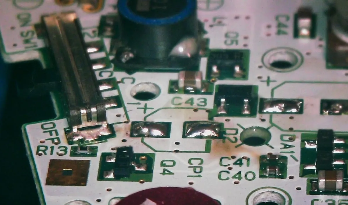
Clean the pads
Section titled “Clean the pads”Clean off any flux residue or burnt flux with cotton swabs and IPA.
Cut a small strip of solder wick with your flush cutters. Apply fresh flux to each capacitor pad and hold the solder wick over the pad with your tweezers.
Heat the top of the solder wick with your iron. Don’t scrape the wick across the pad, as this can tear or lift it. Only press straight down, or gently glide the wick across the pads until all solder is absorbed.
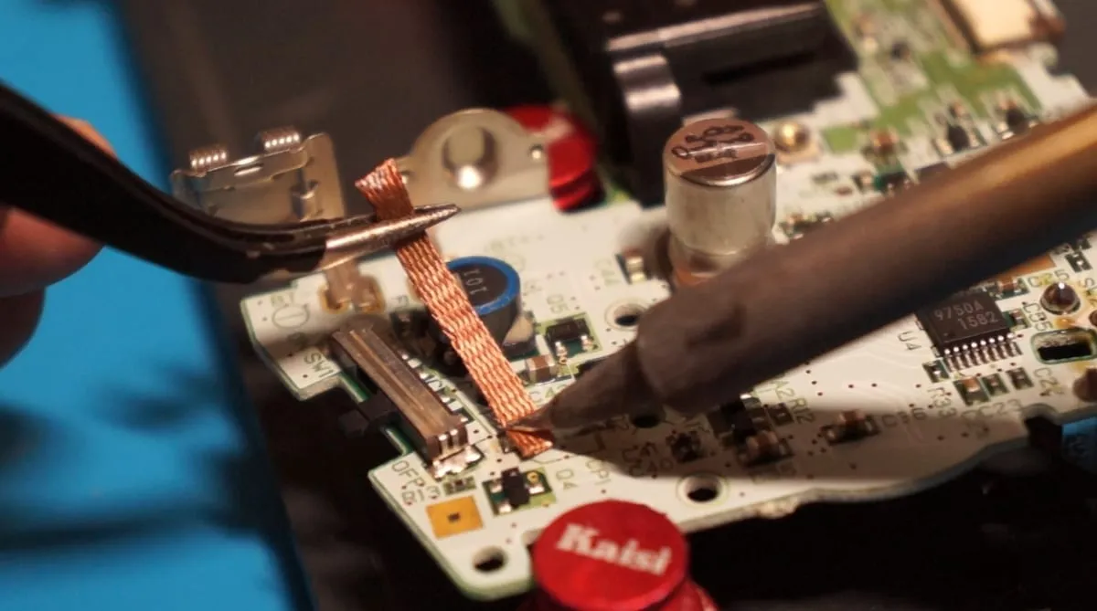
Once more, clean any flux residue or burnt flux with cotton swabs and IPA.
Align the component
Section titled “Align the component”Apply fresh flux to each capacitor pad.
Apply fresh leaded solder to only one of the pads.
Pay attention to the correct orientation of the capacitor (use your reference photo from earlier!), heat the pad with the fresh solder and slide the capacitor into place. Precise placement doesn’t matter yet, you’ll align it in the next step.
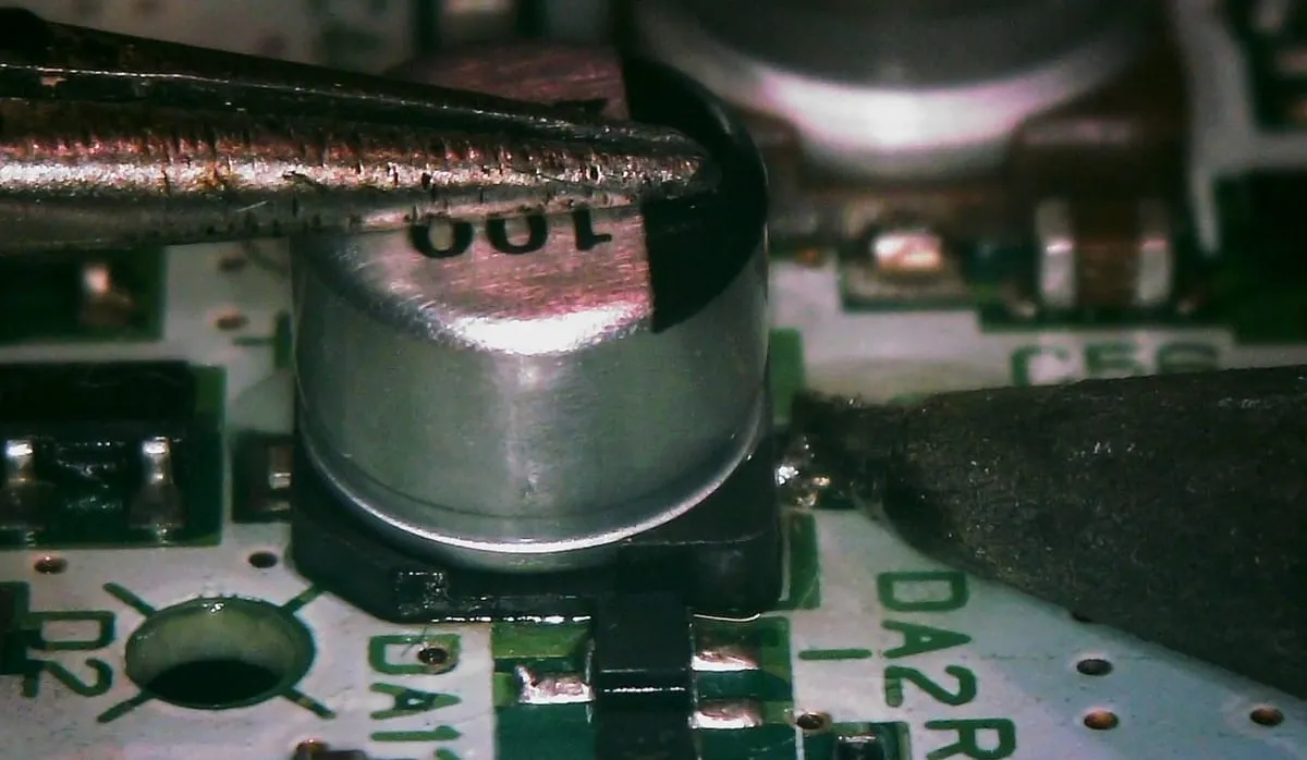
Remove the iron and let the solder cool. Check the placement of the capacitor. If it needs adjusting, heat the joint and move the component as needed. Hold it in place while you remove the heat and the solder cools.
Finish the install
Section titled “Finish the install”Apply fresh leaded solder to the other pad. Try to heat the capacitor leg and the pad at the same time for a proper connection. Work quickly so the capacitor doesn’t get too hot.
Clean off the flux with cotton swabs and IPA.
B) Through-hole capacitors
Section titled “B) Through-hole capacitors”Grab and flip
Section titled “Grab and flip”Grab the capacitor you are removing and flip the board over to reach the solder joints you tinned earlier on the back of the PCB. Apply flux to the capacitor’s solder joints. Gloves and eye protection are a must here!
Heat and remove
Section titled “Heat and remove”Now heat both joints of the capacitor at once while gently pulling on the capacitor in your grip. Your choice of soldering tip makes this step either easier or harder. For larger capacitors you may need to go back and forth between both joints to remove it fully.
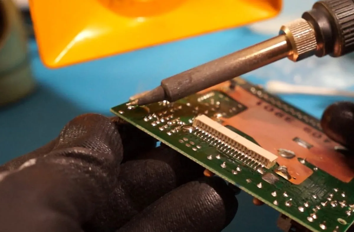
Clean the vias
Section titled “Clean the vias”Cut a small strip of solder wick with your flush cutters. Apply fresh flux to each capacitor via (the holes the capacitor legs were in). Without flux this step is very difficult! Hold the solder wick over the via with your tweezers.
Heat the top of the solder wick with your iron. Don’t scrape the wick across the via. Only press straight down, or gently glide the wick across the vias until all solder is absorbed. You should be able to see clearly through the hole now!
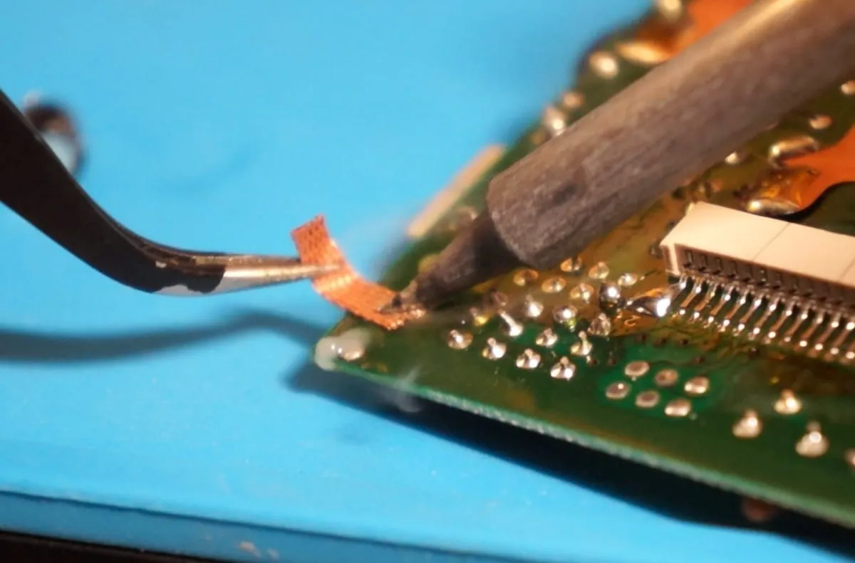
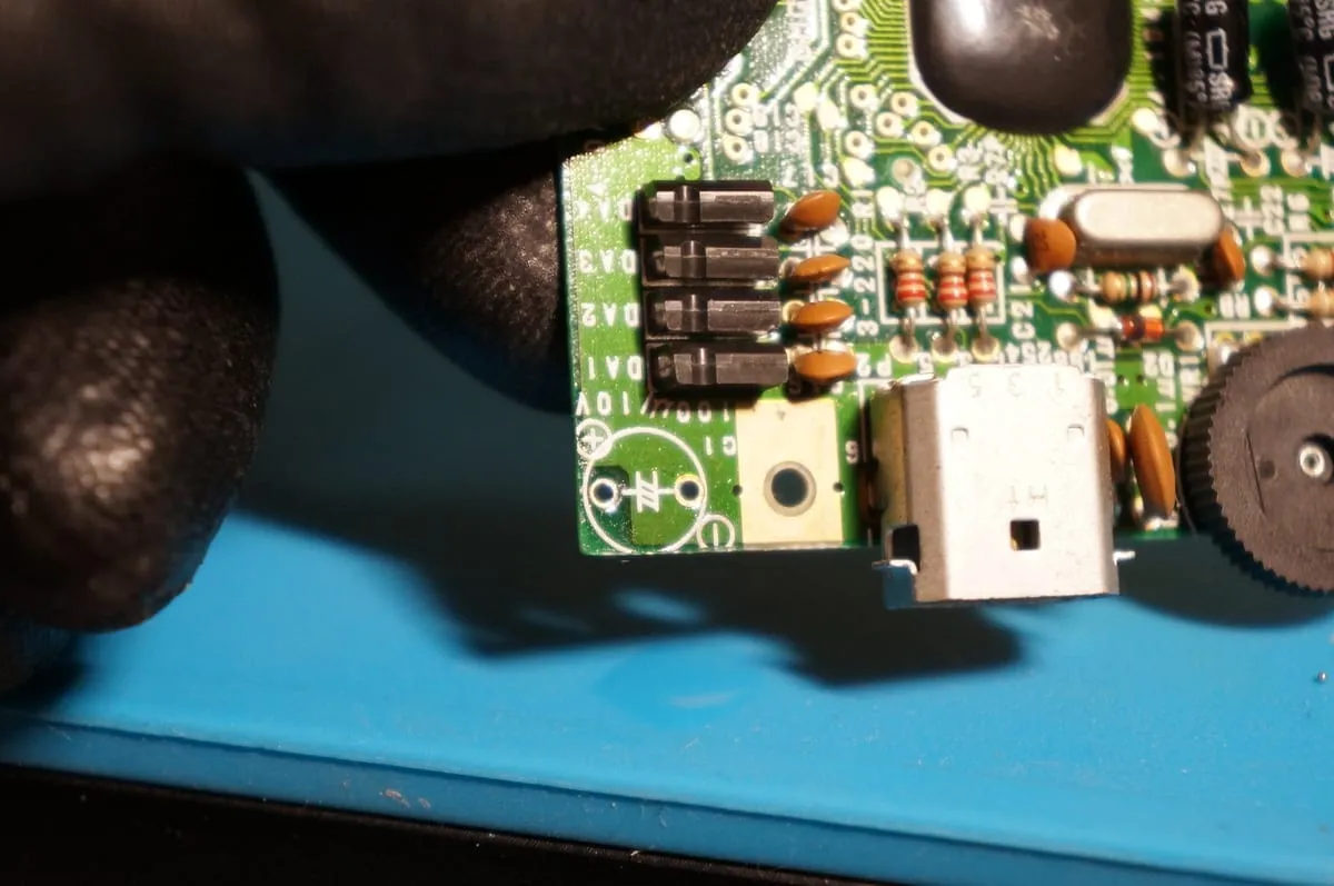
Once more, clean any flux residue or burnt flux with cotton swabs and IPA.
Insert and solder the capacitor
Section titled “Insert and solder the capacitor”Thread the legs of your new capacitor through the clean vias. Make sure the orientation is correct (double-check with your photos!). Bend the legs at an angle to hold the capacitor in place while you solder.
Flip the board over and apply flux where the legs stick out of the PCB. Heat the via and the leg at the same time while adding some fresh solder.
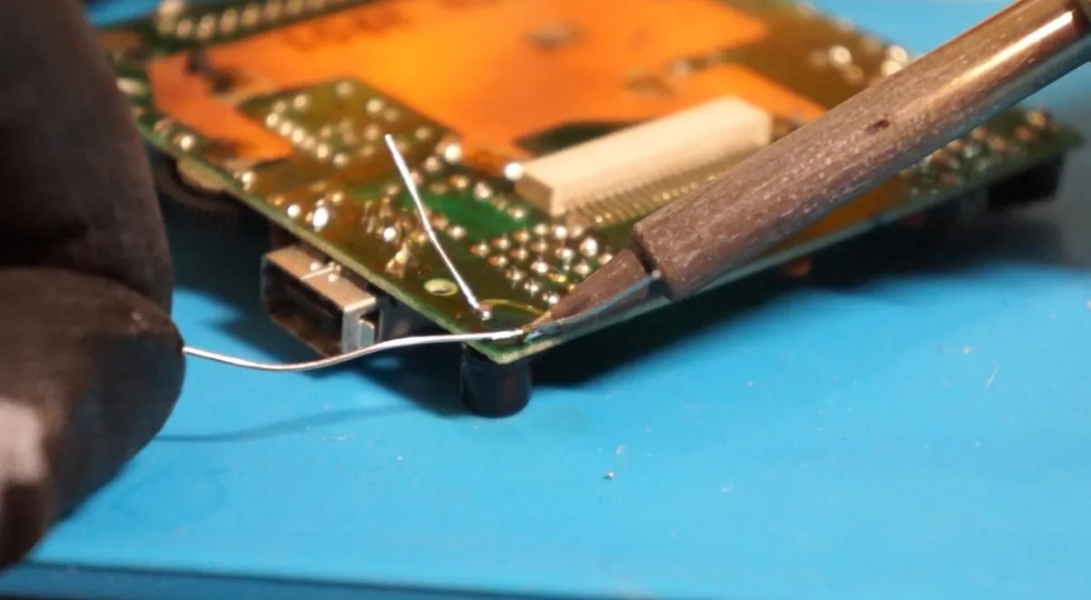
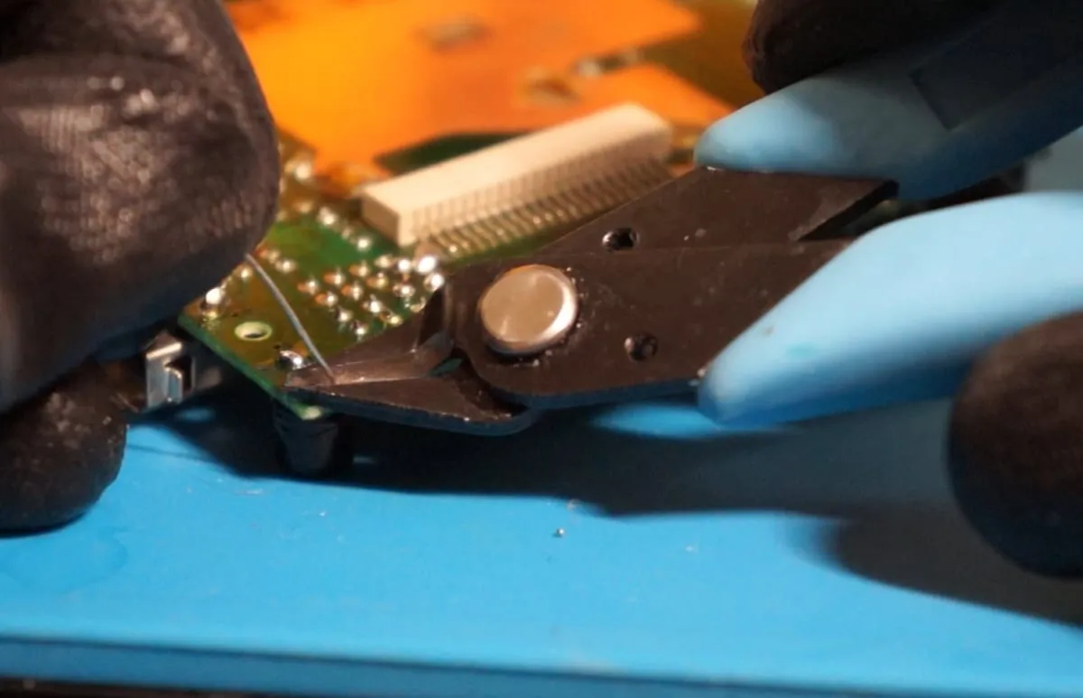
Once the joint looks good, trim the excess leg length with your flush cutters. Clean the joints once more with IPA and cotton swabs.
Completion
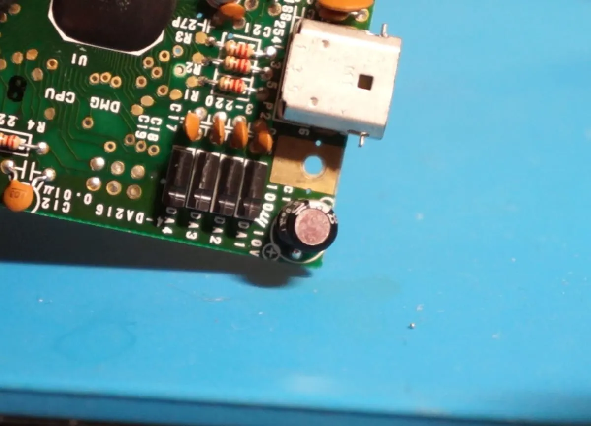
Section titled “Completion”Repeat these steps for every electrolytic cap you want to replace!
Diagnostics: measuring capacitors
Section titled “Diagnostics: measuring capacitors”If you’re unsure whether your console needs a recap, you can measure the voltage at the capacitors. Measurements are taken with a multimeter in DC voltage mode. See your multimeter’s manual for how to set it up.
If your reading is significantly lower than the listed voltages, the respective capacitor most likely needs replacing. All reference values were measured on a known working board that has been recapped.
Game Boy Pocket
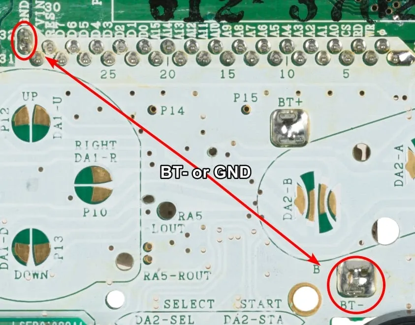
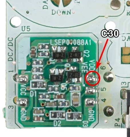
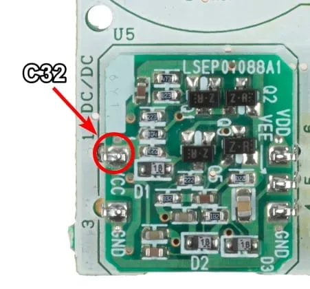
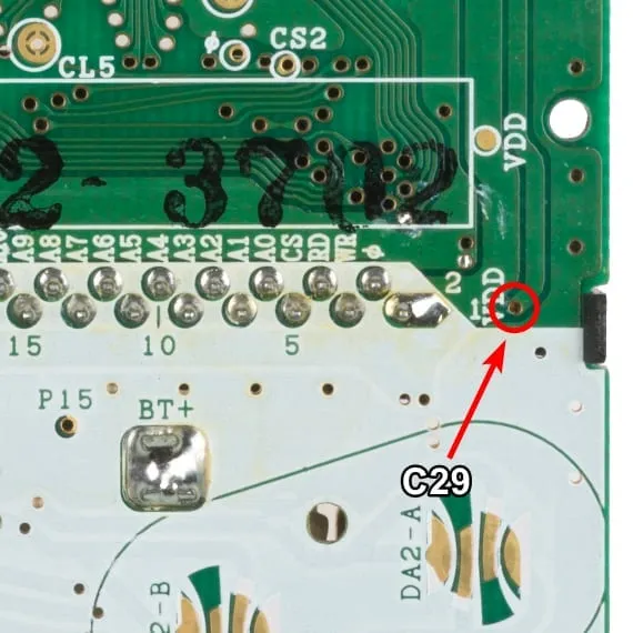
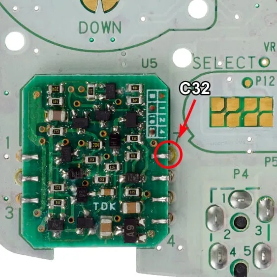
Section titled “Game Boy Pocket”Without a power supply, measuring the capacitors is tricky unless you know exactly where to probe. The test points below let you measure with batteries installed while the board sits in the housing (which blocks the back of the PCB).
Place the black probe on the negative battery terminal, labelled BT- on the PCB. The red probe goes to the point you are measuring. An alternative spot for the black probe is also shown in the picture.
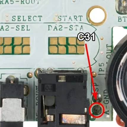
Reference values Game Boy Pocket
Section titled “Reference values Game Boy Pocket”| Capacitor | Voltage |
|---|---|
| C30 | 5 V |
| C32 | 2.93 V |
| C29 | -18 V |
| C31 | 1.25 V |
Board scans: Evan-Amos, Public domain, via Wikimedia Commons

Game Boy Color
Section titled “Game Boy Color”Without a power supply, measuring the capacitors is tricky unless you know exactly where to probe. The test points below let you measure with AA batteries in the Game Boy Color housing (which blocks the back of the PCB).
Place the black probe on the negative battery terminal, labelled BT- on the PCB. The red probe goes to the point you are measuring. An alternative spot for the black probe is also shown in the picture.
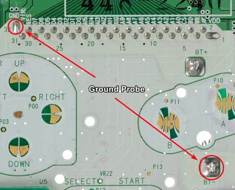
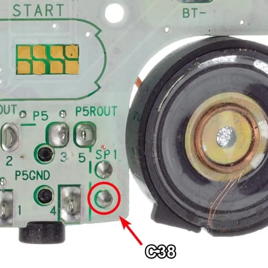
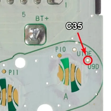
Reference values Game Boy Color
Section titled “Reference values Game Boy Color”| Capacitor | Voltage |
|---|---|
| C38 | 1.35 V |
| C35 | 2.5 V |
| C32 | 5 V |
Board scans: Evan-Amos, Public domain, via Wikimedia Commons

Game Boy Advance
Section titled “Game Boy Advance”Without a power supply, measuring the capacitors is tricky unless you know exactly where to probe. The test points below let you measure with AA batteries in the GBA housing (which blocks the back of the PCB).
Place the black probe on the negative battery terminal, labelled BT- on the PCB. The red probe goes to the point you are measuring.
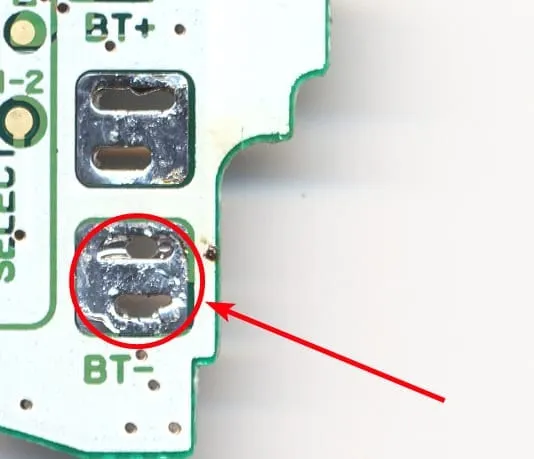
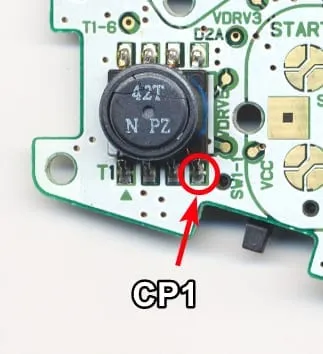
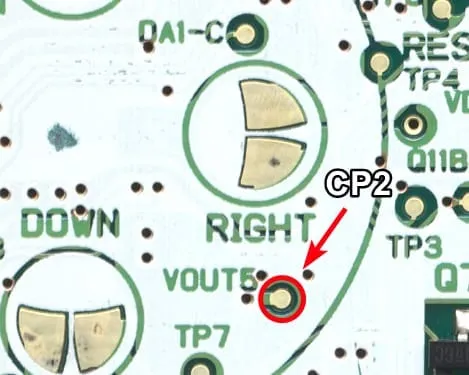
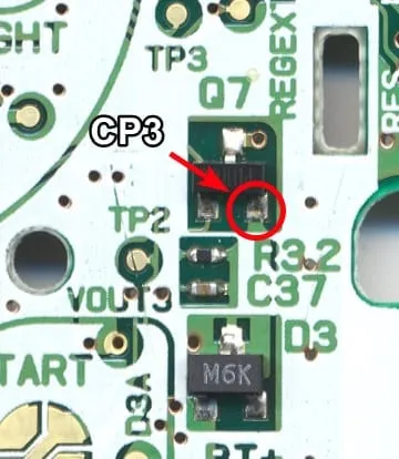
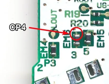
Reference values Game Boy Advance
Section titled “Reference values Game Boy Advance”| Capacitor | Voltage |
|---|---|
| CP1 | 2 V to 3 V |
| CP2 | 5 V |
| CP3 | 3.33 V |
| CP4 | 1 V |
Board scans: circuit-board.de forum, STRIP CLUB PCB Scans
Game Boy Advance SP
Section titled “Game Boy Advance SP”On the GBA SP you measure the voltage directly at the capacitor while the console is powered on. A failing capacitor is a common cause of no audio on a GBA SP.
The measurement is easier with a power supply that clips onto the battery terminals and supplies 3.5 V.
The test must be done with a speaker installed, so it’s easiest to screw the PCB into the front housing to make sure the speaker has good contact.
Place the black probe on the side of the capacitor marked in black, and the red probe on the side labelled ‘+’.
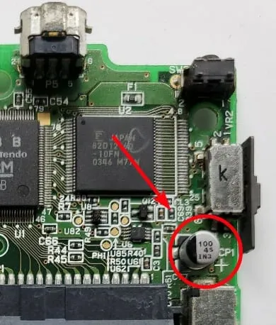
Reference value Game Boy Advance SP
Section titled “Reference value Game Boy Advance SP”| Capacitor | Voltage |
|---|---|
| CP1 | 1.5 V |