
[GBP] RetroSix CleanPower
After installing an IPS kit, an audio amp or both, a Game Boy Pocket often powers down on its own, needs two attempts to power up or behaves unstably. The original voltage regulator can’t deliver enough power for these mods. The CleanPower replaces it and provides a stable 5 V supply. The input voltage (VIN) range is 2.5 V to 12 V.
There is a separate CleanPower for the Pocket and for the Color. For the Game Boy Color, see [GBC] RetroSix CleanPower. How to open the Pocket is covered in [GBP] Shell Disassembly.
The original regulator
Section titled “The original regulator”The original voltage regulator is the small green board sitting on top of the mainboard. From the back you can see the inductor. The inductor and the capacitors for the 5 V rail stay on the board; only the green board is replaced.
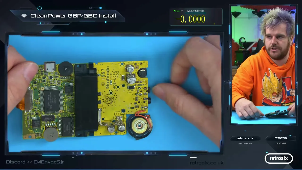
▶ Watch in the video from 0:58
The pins of the regulator board poke through the mainboard. On the input side they are labelled VCC and GND, on the output side VDD (5 V output), VE (LCD voltage) and GND.
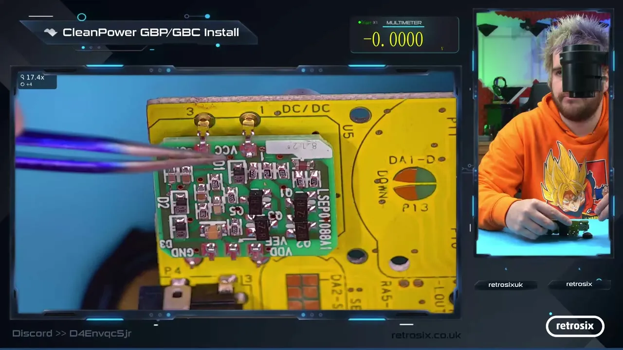
▶ Watch in the video from 1:41
Seen from the side you normally work from, the pinout is:
- Input side: GND and VIN (straight from the battery, after the fuse)
- Output side: 5 V (this rail struggles with heavier mods and is taken over by the CleanPower), negative LCD voltage and GND
The regulator only receives power once the power switch is on. In the video, 3 V arrives at the input, the output measures 5.1 V and the negative LCD voltage is around -18 V.
Which option suits you?
Section titled “Which option suits you?”The negative LCD voltage is only needed by the original screen and some IPS screens (the video mentions FunnyPlaying screens) to set the brightness. That gives you two options:
- CleanPower alongside the original regulator: The CleanPower is soldered in next to the original regulator and supplements the 5 V rail. As it sits on the inductor, you may need a short piece of wire. The original screen or an IPS screen that needs the LCD voltage keeps working. Downside: slightly less efficient, but nothing you’ll notice.
- Remove the original regulator: The best option if you use an IPS screen that doesn’t need the negative voltage (e.g. the RetroSix LCD kits, which run entirely off the 5 V rail). This is a bit more efficient.
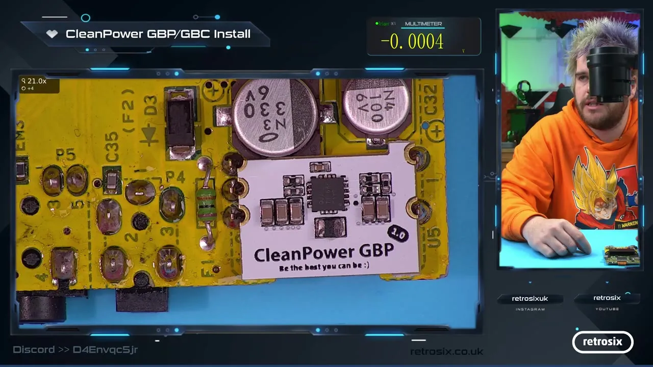
▶ Watch in the video from 4:10
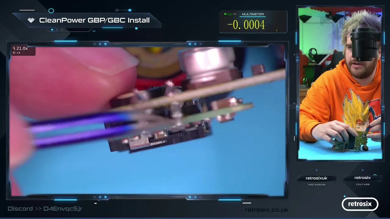
▶ Watch in the video from 5:05
The steps below remove the original regulator and solder the CleanPower in its place. The video still has the original screen installed, so afterwards there is no picture, but there is sound.
Removing the original regulator
Section titled “Removing the original regulator”You don’t need special tools for this. Apply plenty of fresh solder to all regulator pads (the three on one side and the two on the other). Bridging the pads doesn’t matter here; it actually helps with heat transfer.
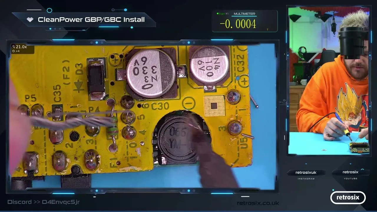
▶ Watch in the video from 6:09
Wedge tweezers under the regulator board and press down very gently with your thumb. Then heat the two pads alternately so both are molten at the same time. The board only comes loose once neither pad is still solid.
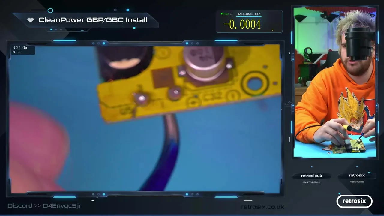
▶ Watch in the video from 6:28
The other side is easier: hold the board, lay the iron across all three pads and heat them at once. The board just drops out. Keep the old regulator in case you need it later.
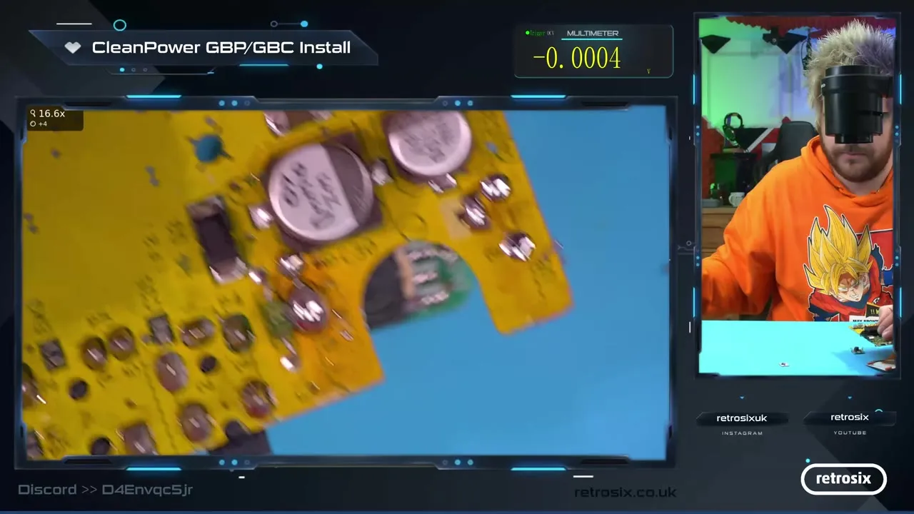
▶ Watch in the video from 7:24
Cleaning the pads
Section titled “Cleaning the pads”Clean your iron in brass wool. If there is a lot of solder on the pads, tilt the board, heat the solder and tap the board so the solder rolls off. You can also remove excess solder with desoldering wick. Flatten the solder on the pads.
Important: there must be no bridge between the GND pad and the VIN pad.
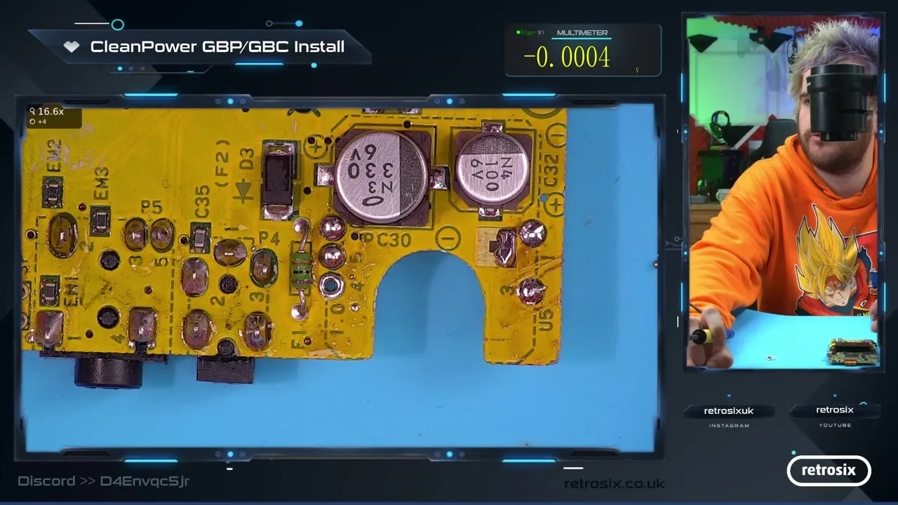
▶ Watch in the video from 8:18
Soldering in the CleanPower
Section titled “Soldering in the CleanPower”Place the CleanPower where the old regulator was; it fits the pads exactly. Add a little solder to one pad and tack the first contact. If the board sits slightly askew, reheat that pad and twist the CleanPower until all pins line up with their pads.
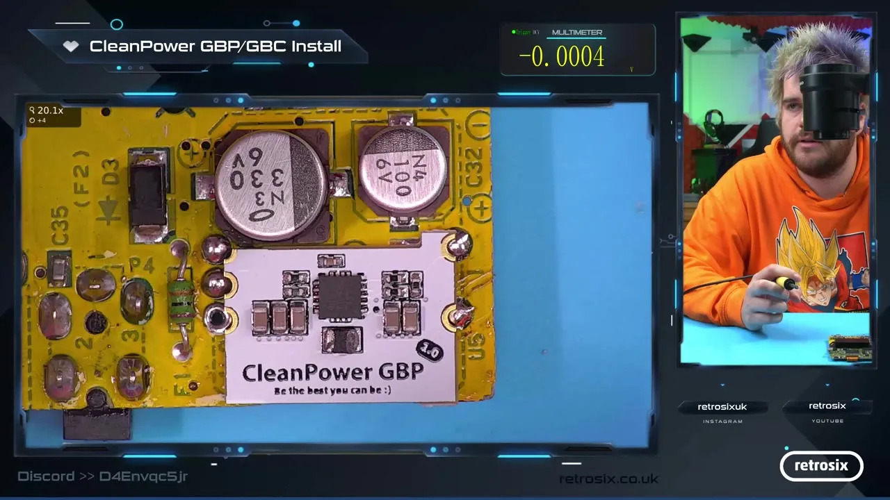
▶ Watch in the video from 8:40
Then solder the remaining pads by applying solder to the pad and letting it flow onto the CleanPower. The corner pad is a bit harder to see but solders just the same.
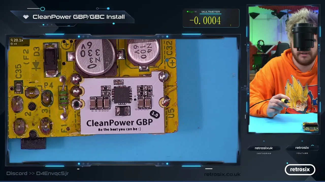
▶ Watch in the video from 9:07
Checking continuity
Section titled “Checking continuity”Before powering up for the first time, use your multimeter in continuity mode to make sure there is no short:
- The two GND pads are connected to each other (beep).
- VIN is not connected to GND. A bridge to the metal pad under the CleanPower would cause a short here.
- Input and output are not connected. A short beep is normal (the IC charging), a continuous beep means there is a problem.
- GND at the bottom right is not connected to the second pad at the top.
Only the two GND points may be connected to each other, nothing else.
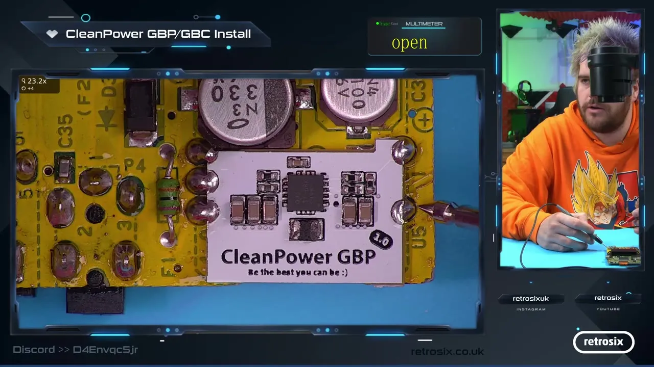
▶ Watch in the video from 10:21
Testing
Section titled “Testing”Switch the Pocket on. Since the negative LCD voltage is now missing, the original screen shows no picture, but you can hear the audio. At the input you measure the battery voltage again (3 V in the video), at the output a steady 5 V.
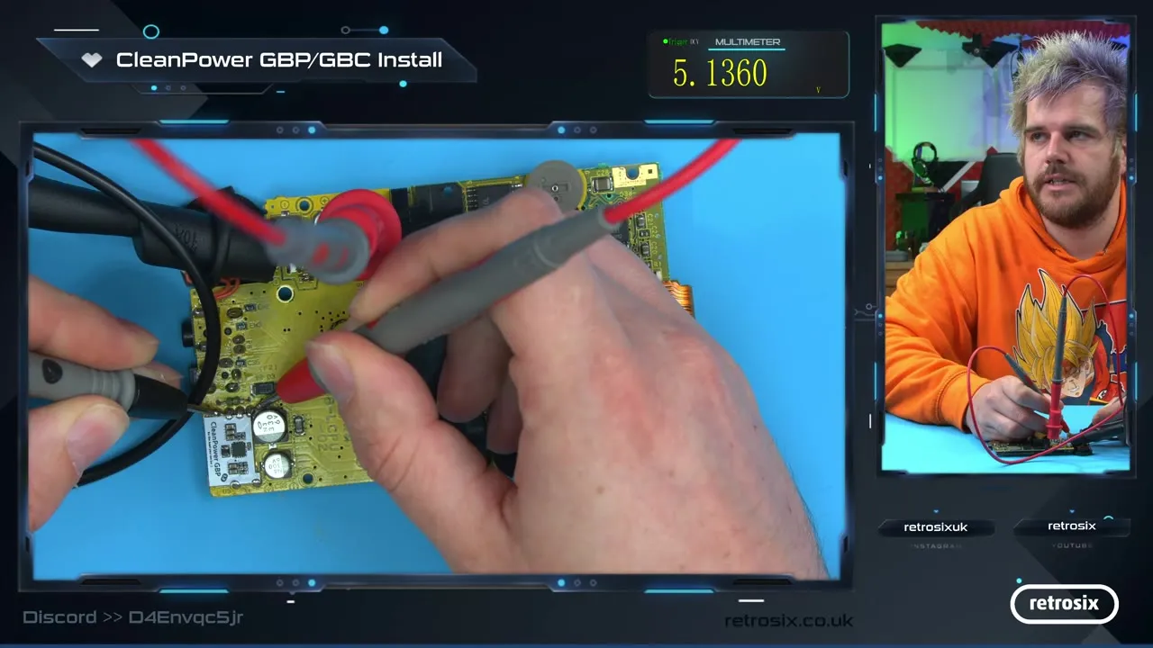
▶ Watch in the video from 11:56
With the CleanPower, even heavily modded consoles run stably, for example with an Everdrive, IPS screen, audio mod and CleanJuice combined.