
[SNES] RetroSix CleanRGB + EdgeBuster
The SNES already outputs RGB from the AV port, but with a DC offset that puts the voltage levels off for most monitors.
General information on the CleanRGB, how to tune the pots and the resistance values for SNSP-CPU-02 and SNS-CPU-GPM-02 are on the RetroSix CleanRGB Universal page.
Watch the install:
Most people solve this with custom RGB cables with AC coupling capacitors and resistors. That works, but it’s far from perfect: it brings all the problems AC capacitors add (field droop, tilt, common-mode noise coupling from the receiver side and more).
The CleanRGB instead fixes the console itself so it outputs IRE-correct voltage levels and signals. The cable is then a pure DC cable with direct connections, no hidden capacitors, sync strippers, resistors or other magic. The result is clean RGB signals that aren’t affected by your cable, receiver or noise. The matching RetroSix cable is the SNES/N64 CleanRGB SCART cable.
Overview
Section titled “Overview”This install involves:
- Getting the RGB and Sync inputs from the S-RGB or PPU2 to the CleanRGB
- Severing the stock RGB and Sync traces to the AV port
- Wiring the CleanRGB RGB and Sync outputs back to the AV port
- Tuning the CleanRGB for correct IRE levels
Wiring the RGB inputs
Section titled “Wiring the RGB inputs”Install the CleanRGB Universal board in the SNES. Tap the RGB and Sync inputs directly from the PPU2 or from specific transistors connected to the PPU2.
SNS-CPU-GPM-02
Section titled “SNS-CPU-GPM-02”On the SNS-CPU-GPM-02 variant, these are the connection points:
- R: bottom left Q3 (goes to PPU2 pin 95)
- G: bottom left Q5 (goes to PPU2 pin 96)
- B: bottom left Q7 (goes to PPU2 pin 97)
- CSYNC: via to the left of Q3, the bottom of 3 vias in a row, after the 2 vias stacked one on top of the other (goes to PPU2 pin 100)
- 5V: pin 27 of the cartridge connector
- Ground: pin 5 of the cartridge connector
- Outputs to the AV port pins (AV port traces cut)
SNSP-CPU-02
Section titled “SNSP-CPU-02”On the SNSP-CPU-02 variant, these are the connection points:
- R: bottom left Q3 (goes to PPU2 pin 95)
- G: bottom left Q5 (goes to PPU2 pin 96)
- B: bottom left Q7 (goes to PPU2 pin 97)
- CSYNC: goes to PPU2 pin 100
- 5V: pin 27 of the cartridge connector
- Ground: pin 5 of the cartridge connector
- Outputs to the AV port pins (AV port traces cut)
All versions
Section titled “All versions”The CleanRGB works in every SNES version, including the Jr models. Every SNES has an S-RGB or PPU2 chip.
R, G and B In go to the CleanRGB inputs. Take 5V from any 5V point such as the AV port or the regulator, and ground from a nearby ground.
The SNES Jr has no RGB connections to the AV port, so nothing needs to be cut.
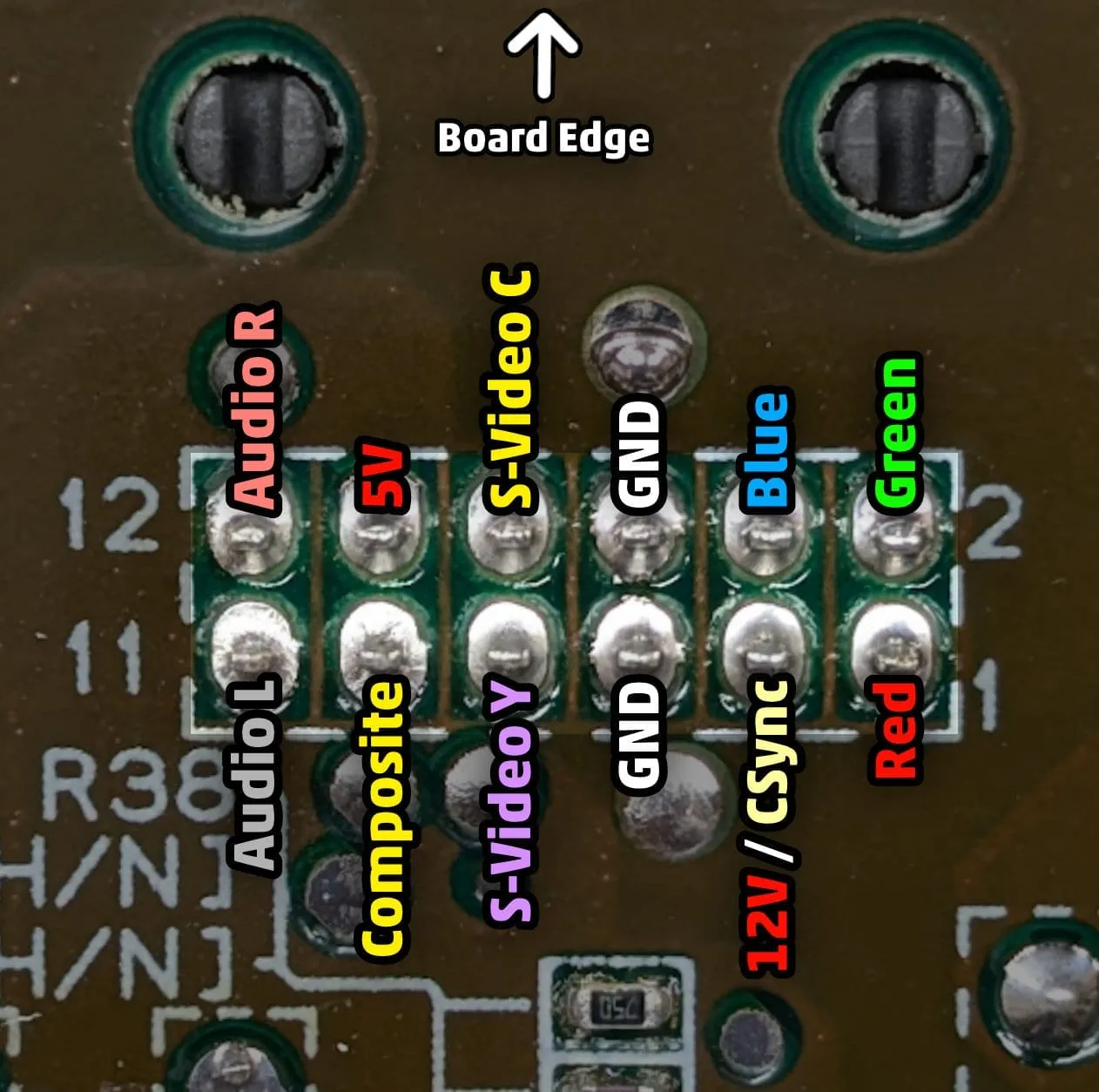
Disconnecting the AV port
Section titled “Disconnecting the AV port”Next, disconnect the AV port from its existing RGB connections.
The simplest way is to expose the traces running from the AV port pins and cut them. Every board revision has a different layout, so gently scrape away the solder resist to reveal the copper traces coming off the AV port pins and cut the R, G, B and Sync traces.
For example, here are the cuts on an SNS-CPU-GPM-02.
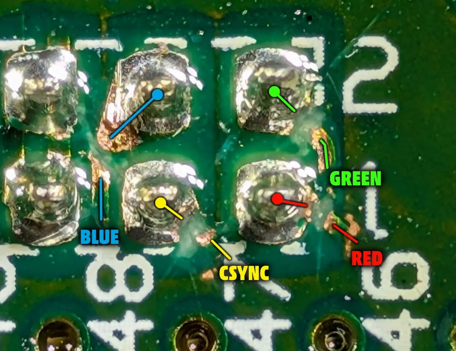
Once done, it’s a good idea to cover the exposed copper with conformal coating or nail varnish to seal it.
Connecting the CleanRGB output
Section titled “Connecting the CleanRGB output”Now wire the RGB and Sync outputs to the AV port pins.
EdgeBuster
Section titled “EdgeBuster”If you have a non-1-CHIP SNES, bridge the EdgeBuster pads on the bottom right of the CleanRGB to enable edge sharpening.
Tuning
Section titled “Tuning”How to set the pots (by eye, with a multimeter or an oscilloscope) is explained on the RetroSix CleanRGB Universal page.