
[GG] RetroSix CleanScreen V4
The CleanScreen V4 replaces the original Game Gear LCD with a 640x480 IPS display. The picture is integer scaled, so every pixel is the same size and fine patterns don’t shimmer. The board is driven by a Raspberry Pi microcontroller (RP2350B) instead of an FPGA. A triple frame buffer prevents tearing. The V4 supports all Game Gear revisions from VA0 to VA5 and connects with flex cables, no single wires needed. The firmware can be updated.
For the older V2 and V3 versions see [GG] RetroSix CleanScreen V2/V3.
Box contents
Section titled “Box contents”- 1x CleanScreen V4 board
- 1x IPS LCD
- 2x Wirefree Install Kit (1 chip and 2 chip)
- 1x LCD holding frame
Used in the video: soldering iron, flux, hot air station, tweezers, flush cutters and metal snips or a sturdy pair of scissors.
Installation
Section titled “Installation”In the video, Mike from RetroSix installs a CleanScreen V4 in a customer’s Game Gear. The mainboard is already out of the shell.
Remove the original screen
Section titled “Remove the original screen”-
Remove the fluorescent tube: Snip the two thin wires of the old backlight or desolder them from underneath. Undo all screws of the holder, then lift the tube out.
-
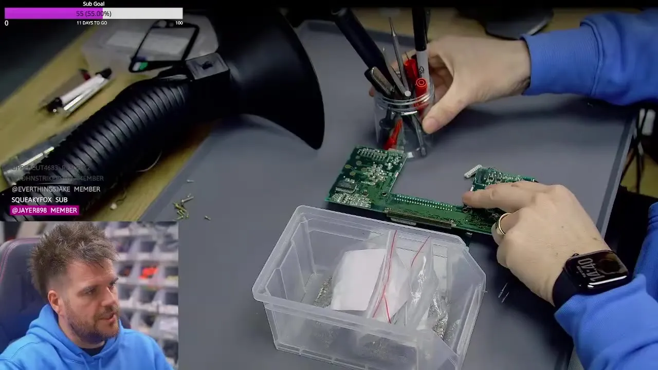
Bend the board into an S shape: Gently bend the screen board into an S shape and wedge it in on both sides so it can’t move. This makes the old LCD’s flex cable want to lift off its solder joint by itself.
-
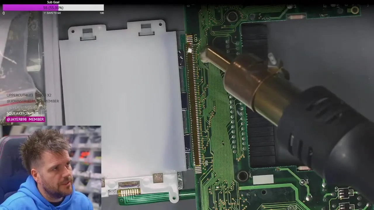
Release the LCD: Preheat the board briefly with hot air. The temperature isn’t critical. Then slowly move the hot air along the flex cable. It pops off pin by pin without you touching it. Pads and pins stay undamaged, so you could solder the original LCD back in later.
-
Peel off the tape: There’s electrical tape over the pins. Peel it off slowly while the board is still warm. Then check that there are no shorts between the pads.
Disable the old backlight circuit
Section titled “Disable the old backlight circuit”-
Remove the fuses: Snip the fuses off or desolder them from underneath. Often only the legs come out of the brittle fuse body.
-
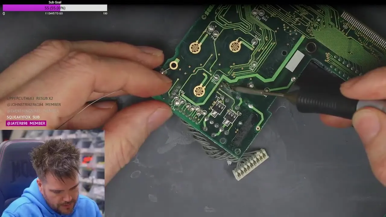
Remove the inductor: The inductor (L2), together with the transformer, a capacitor and the fuses, generates the high voltage for the fluorescent tube and has to go. Flood both of its pins with solder from the opposite side and it usually drops out. If not, give it a tap.
-
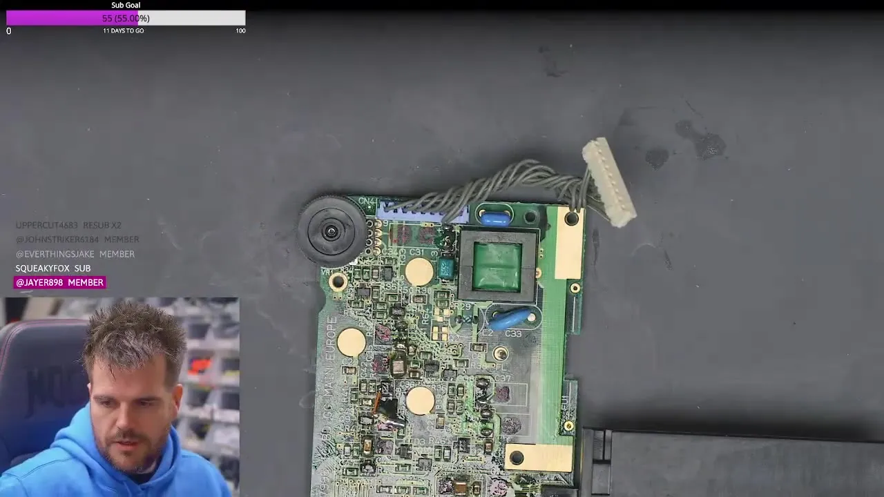
Remove the parts at the brightness wheel: There are four small components next to the brightness wheel. According to RetroSix only the two resistors technically need to come off, but Mike usually removes all four. Don’t use hot air here or you’ll melt the wheel.
-
Clean the screw holes: The CleanScreen board will sit where the original LCD bracket was screwed down. Remove any excess solder around these holes so the surfaces are flat.
Solder the flex cables
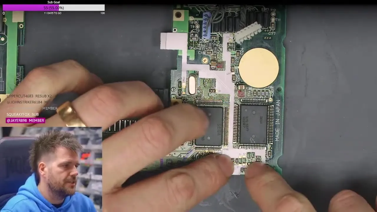
Section titled “Solder the flex cables”The Wirefree Install Kits connect the mainboard to the CleanScreen board with flex cables. The flex cables are soldered onto pads on the mainboard, but you don’t need any single wires. There’s one kit for 1-chip and one for 2-chip mainboards, each with a cable for the left and the right side. The cables of the first batch aren’t labelled. The pictures under Identifying 1-chip vs 2-chip show how to tell the boards apart. The board in the video is a 2-chip mainboard.
-
Find the right cable: Test fit the flex cable. With the right cable every pad sits over its spot, for example PCLK, T10 and the row of pins further down. If one of them doesn’t line up, take the cable from the other kit.
-
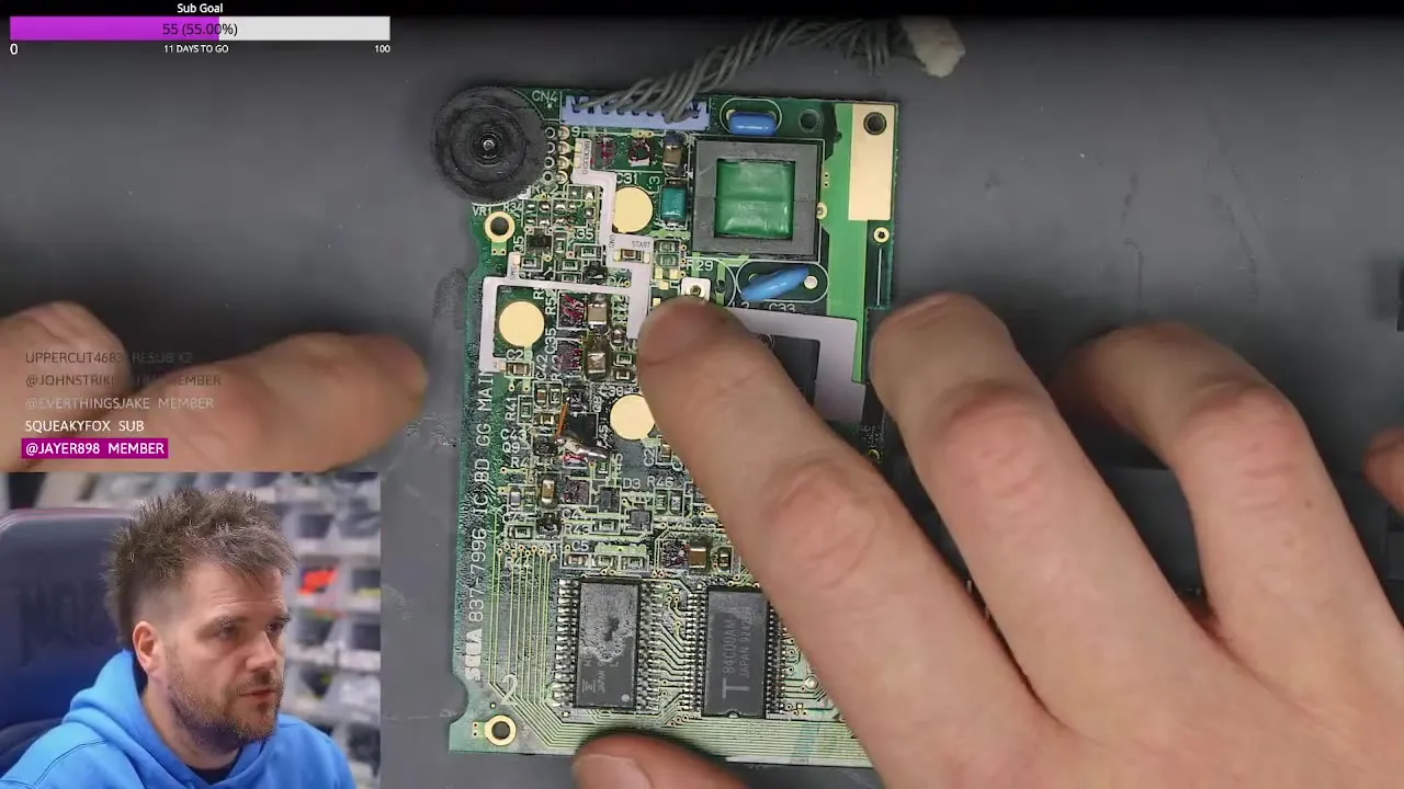
Other side: On the other side both cables fit. The only difference is a notch at the contact for the SMS resistor. If that resistor is on your board, make sure this contact gets soldered. Without it, the CleanScreen doesn’t know it’s in Master System mode.
-
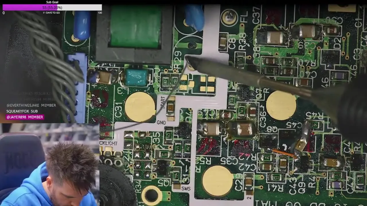
Solder the first side: Tack the cable down at the 5 V pad first and check that all other pads line up. Then solder the pads at the very bottom: pre-tin the pad, let it cool for a moment, then add a blob of solder. Hold the cable down with tweezers if needed. Then do SMS and the remaining pads on this side, one of them sits over a capacitor. Watch out not to melt any plastic near the brightness wheel.
-
Tack the second side: Tack T10 first here, then the bottom end of the cable. Once both ends are in place, the other pads usually line up on their own.
-
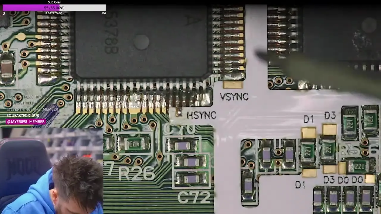
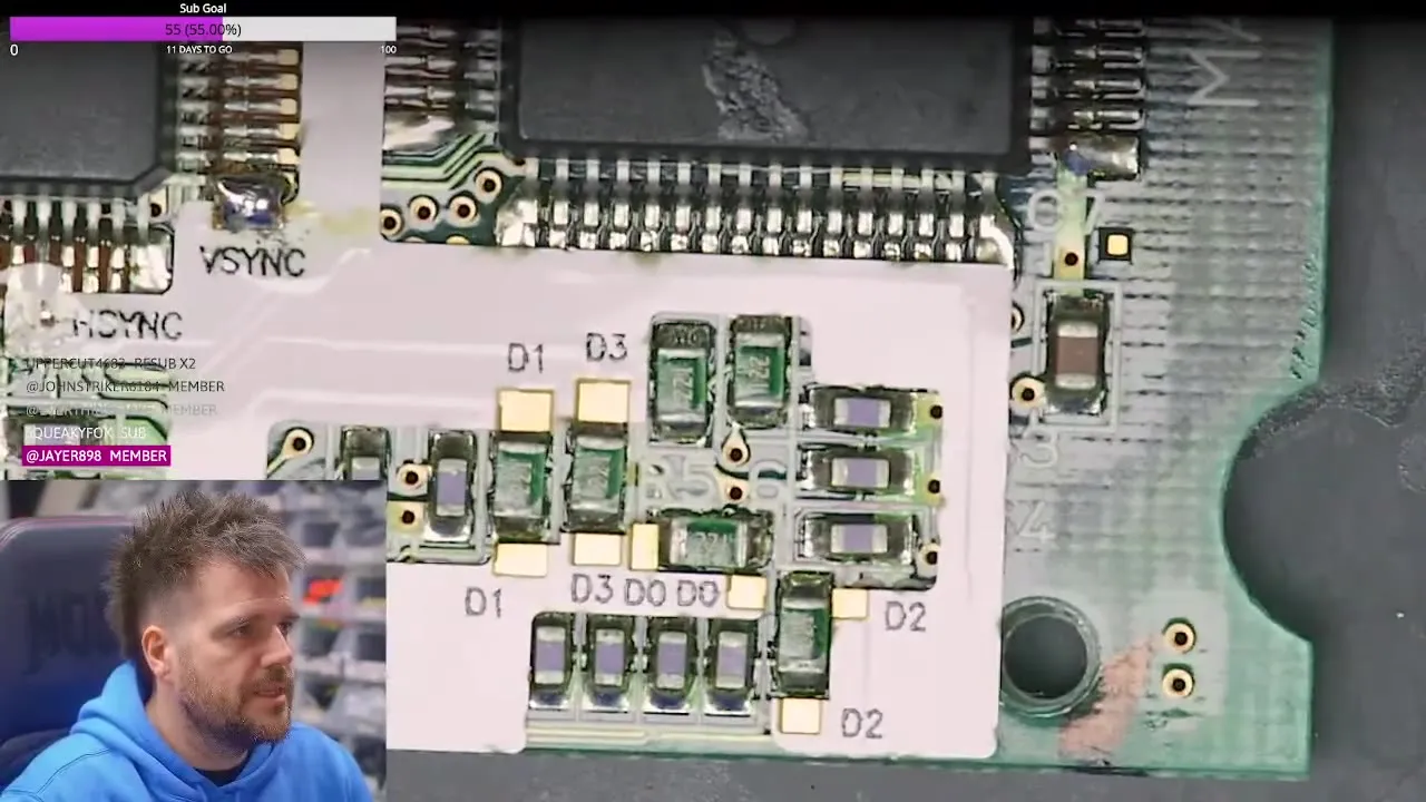
Solder HSYNC: The HSYNC tab is loose and goes onto pin 5 of the row (count 1, 2, 3, 4, 5). Flux the board, fill that pin with solder, hold the tab on it with tweezers and heat it. The tab has copper on its underside too, so the solder flows underneath by itself. Being slightly off angle is fine.
-
VSYNC and data lines: Just flood VSYNC with solder. The data line pads each sit over a resistor and bridge it. If a resistor comes off in the process, don’t worry about it. You can also remove the resistors first and bridge the two pads directly.
-
Check: Make sure everything is soldered: data lines, HSYNC, VSYNC, 5 V, Left, T10, SMS and PCLK. You can spot PCLK by its thick trace. You can solder to either of the two pads or between the two resistors, it’s all the same line.
Mount the display and board
Section titled “Mount the display and board”-
LCD in the frame: The IPS LCD is stuck into the 3D printed holding frame, with the LCD flex cable coming out at the top.
-
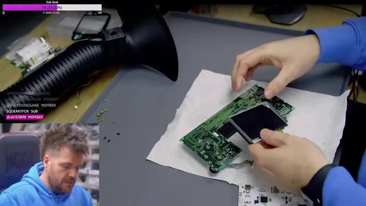
Align the frame: The frame has the shape of the original LCD bracket and goes on the back of the screen board at its four screw holes. Flip everything over and look through the holes to check that the holes in the frame line up with the ones in the board.
-
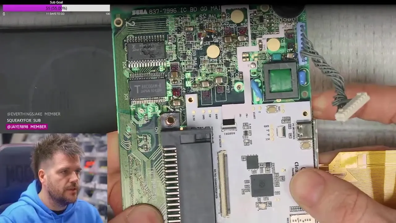
Place the board: Put the CleanScreen board on top, under the LCD flex cable. So the board sits between that flex cable and the display.
-
Screw it down: Hold everything still and drive in one of the small black screws from the kit, then the diagonally opposite corner. If you struggle with the alignment, shine your phone torch from underneath: once you can see light through the hole, it’s lined up. Then put in the last two screws.
-
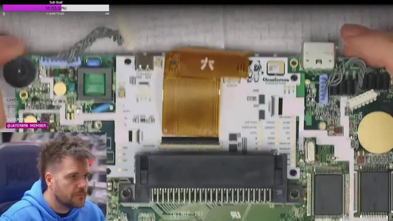
Connect the cables: Plug the two flex cables from the mainboard into the CleanScreen board, then the LCD flex cable. A slight twist in the LCD cable is normal. Handle the LCD cable very carefully, it tears easily.
-
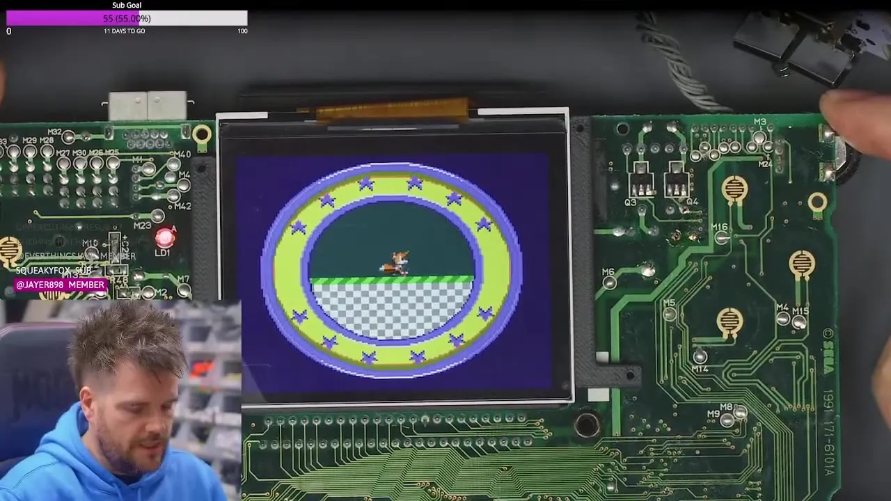
Connect the power board, insert a game and switch the Game Gear on before reassembly. You can leave the audio board out for this. Check the picture and the brightness wheel. See also How do I test the LCD.
Shell modification
Section titled “Shell modification”-
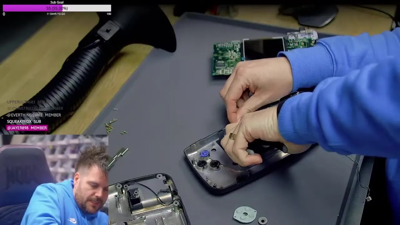
Trim the screw post: There’s a screw post at the top of the front shell. Cut it flush with the shell using flush cutters. This is the only change to the shell. If you leave it, the screw presses against the new lens and cracks it right at that spot.
Metal shield modification
Section titled “Metal shield modification”-
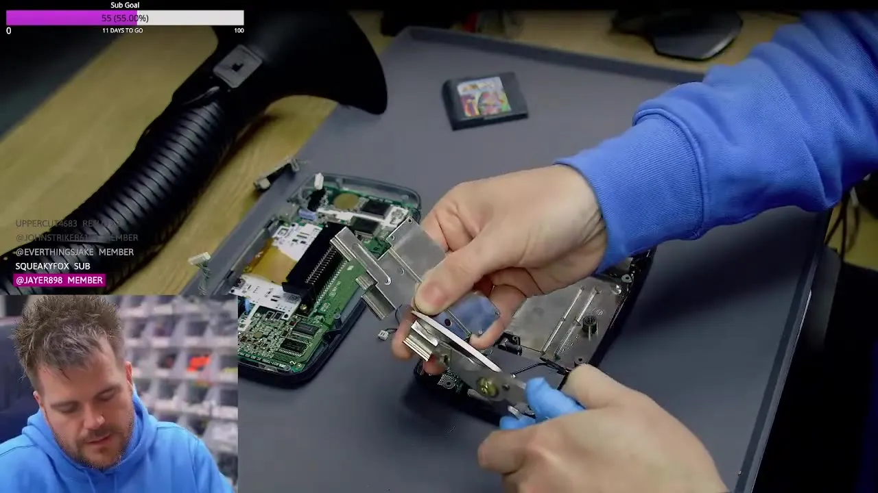
Cut off the flaps: The metal shield over the cartridge slot has flaps at the top that would otherwise get in the way. Cut them off with metal snips or a sturdy pair of scissors. Exactly where you cut doesn’t matter. Some shields, for example the ones in RetroSix shells, don’t have these flaps.
-
Optional: You can also cut off the piece that reaches over the capacitors of the audio board. It serves no purpose and only stops you from removing the audio board without taking the shield off.
Final assembly
Section titled “Final assembly”-
Fit the mainboard: Leave the protective film on the LCD until everything is in place. Feed the brightness wheel through its opening in the shell first, then lower the board until it clicks in. Check that all buttons sit in their holes.
-
Screw it together: Put in the small screws, starting with two diagonally opposite ones. Since four holes now hold the black CleanScreen screws, you’ll have four original small screws left over. Then the two big screws.
-
Back half: Refit the audio board, put the trimmed metal shield over it and route the speaker wire under the board as originally. Finally screw down the power board.
Controls
Section titled “Controls”- Open the OSD menu: hold Start + 2 + Left.
- Navigate: with Left and 2.
- Select: with Start.
- Brightness: with the original contrast wheel. On the V4 the wheel is digital: the board reads the wheel position and generates the brightness itself, current no longer flows through the wheel.
More features:
- Picture modes: infinity scaling, pixel perfection and integer scaling, plus IPS look, scanline emulation and pixel grid.
- With the RetroSix RePCB mainboard and its region switch, the Game Gear runs at either 50 or 60 Hz.
- Output for NeoPixel LEDs.
Pro version
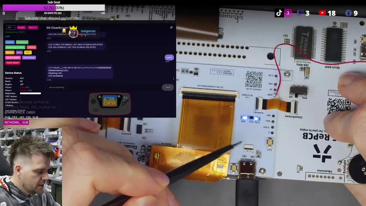
Section titled “Pro version”The Core version can be upgraded to Pro on a computer, see cleanscreen.retrosix.co.uk. The board connects to the PC via USB. In the development video, the board’s four USB connection points were wired to a USB port by hand for this.
▶ Watch in the video from 52:40
Troubleshooting and tips
Section titled “Troubleshooting and tips”- Picture noise or image errors: RetroSix recommends flashing the latest firmware via ggcs.retrosix.co.uk.
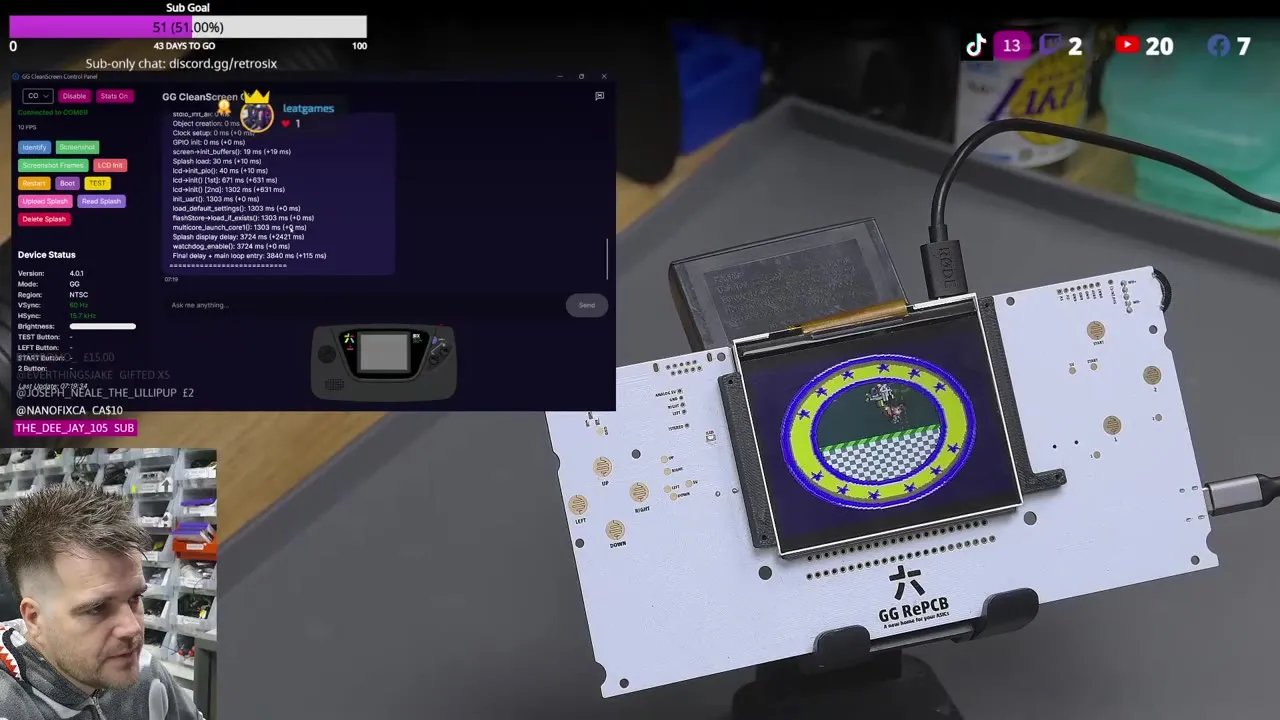
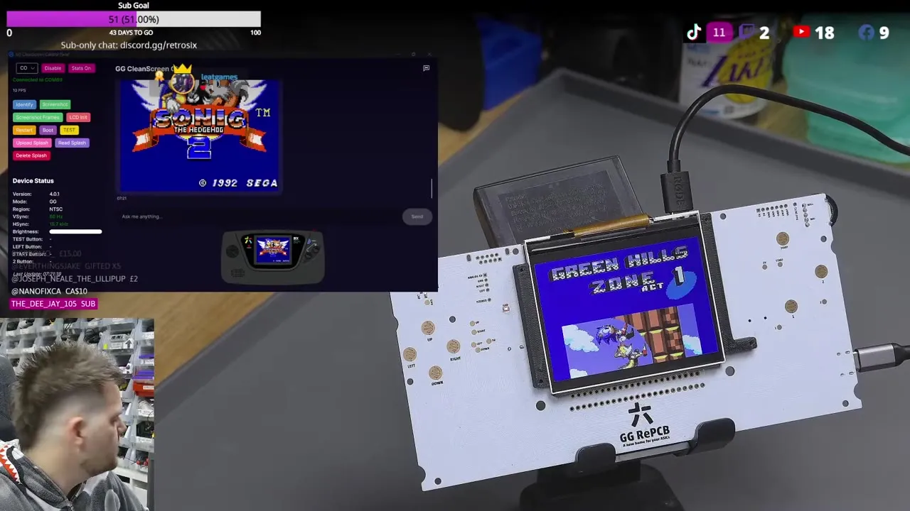
- Diagnostics with the PC software: The PC software shows which buttons are pressed, whether a Game Gear or Master System game is detected, which region is set and whether HSYNC and VSYNC arrive at the right frequency. You don’t need a multimeter or an oscilloscope for these checks.
- Faulty LCD or faulty signal? The PC software can grab a screenshot straight from the frame buffer. If the screenshot looks fine but the picture on the LCD doesn’t, the LCD is at fault. If the screenshot is already broken, the problem lies before the display.
▶ Watch in the video from 17:05
▶ Watch in the video from 18:50
Videos
Section titled “Videos”The installation starts at 1:47:31 in the stream:
Development stream with prototypes and the PC software: