
[GBC] Installing the FP RetroPixel 2.0 Blank
The RetroPixel 2.0 IPS Kit by FunnyPlaying comes in 2 variants: Laminated (=display lens industrially bonded to the LCD) and Blank (without display lens). This guide covers the Blank variant.
Foreword
Section titled “Foreword”- Make sure to run a function test , BEFORE you install the IPS kit! No warranty claims can be accepted for kits that have already been installed. You can see how to test the kit externally here: How do I test the LCD
- The LCD is very fragile and sensitive to pressure, impacts, etc. Please be especially careful when handling the LCD during installation
Preparation
Section titled “Preparation”The kit contains the following components
To open the shell you need
You can find suitable tool kits here
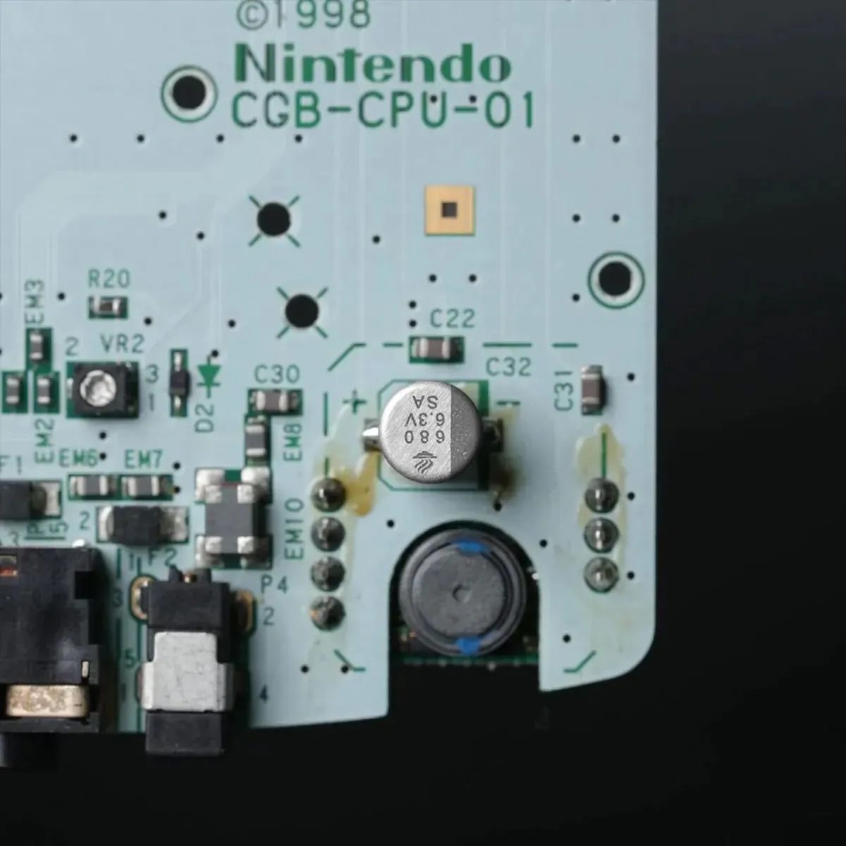
When doing an LCD mod, the 100uF capacitor should be replaced with a 680uF capacitor to reduce noise.
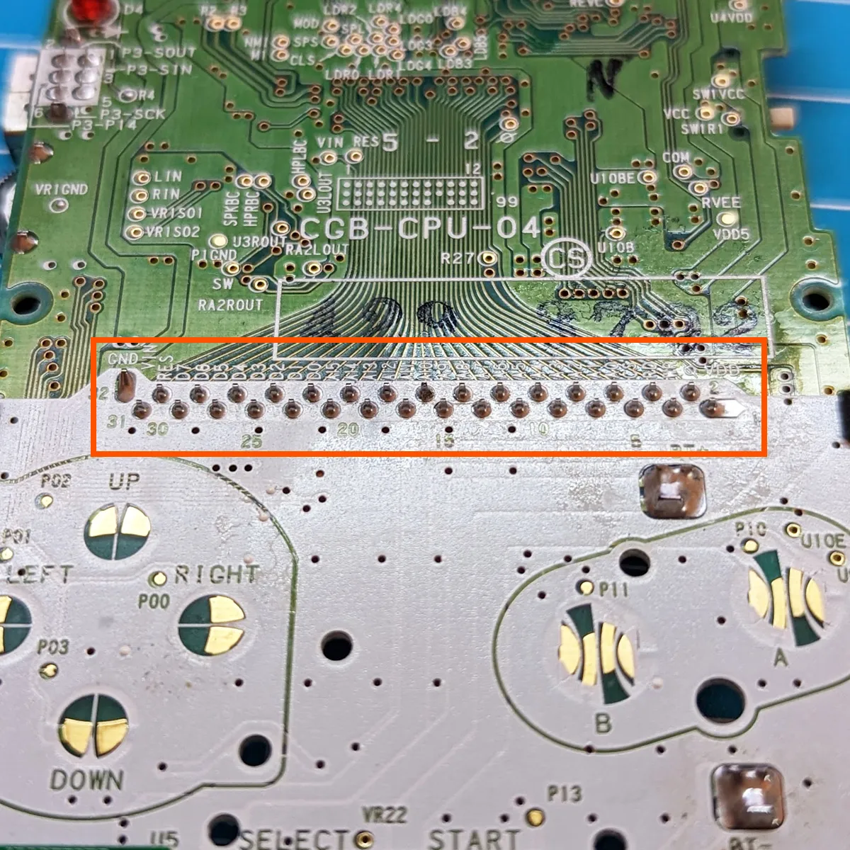
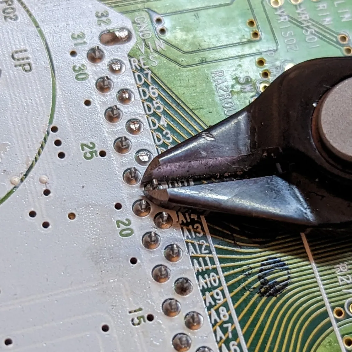
The pins of the cartridge port can press against the LCD, which can cause permanent damage. That’s why the pins have to be trimmed as short as possible with flush cutters. Watch out for flying pieces and protect your eyes!
Preparing the shell
Section titled “Preparing the shell”If you are using an original OEM or non-IPS-ready shell, you need to make some modifications so that the larger LCD of the Q5 XL kit fits. You can find details here: [GBC] Trimming the shell
Pre-trimmed or IPS-ready shells can be used without modifications. On RetroSix shells, the pins around the LCD opening have to be removed: [GBC] Trimming RetroSix shells
Installation
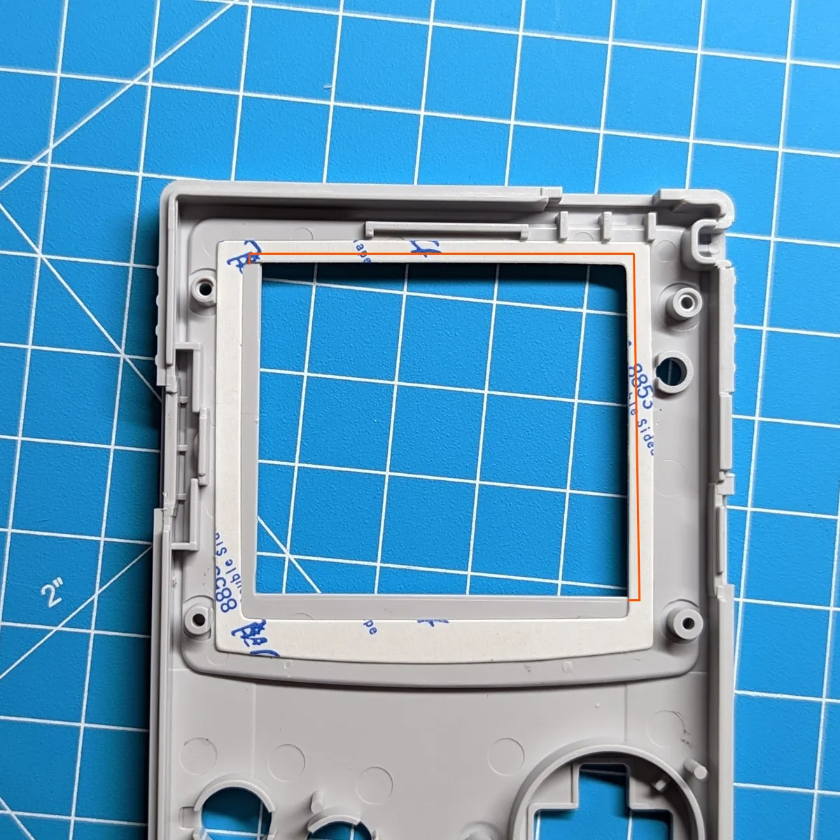
Section titled “Installation”First, apply the included adhesive tape, which will prevent the LCD from shifting after installation. The area in the middle must be completely covered.
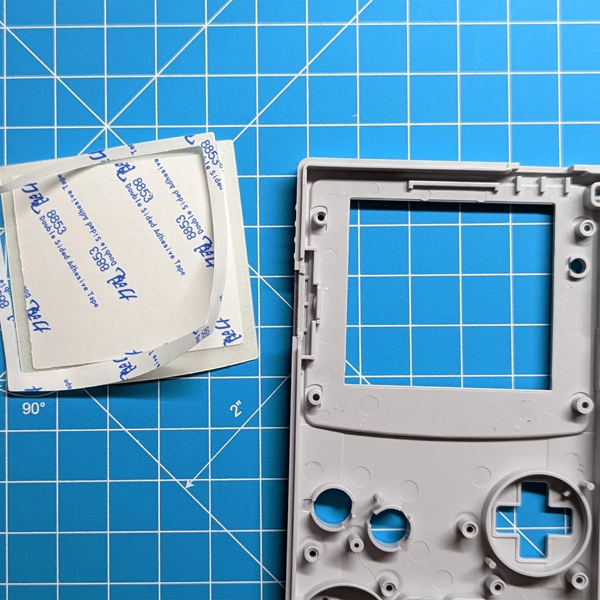
If part of the tape sticks out into the viewing window, trim it accordingly.
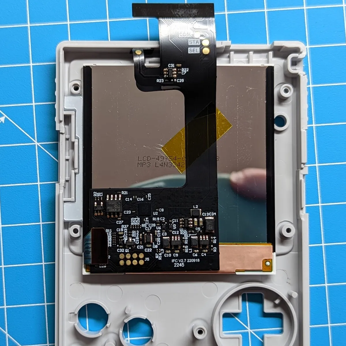
Next, remove the protective film from the LCD and gently place the LCD in position. Stick the black insulation film onto the back of the LCD. Pay attention to the alignment of the display, it should sit straight in the shell. Use nearby shell edges as a reference or use the optionally available positioning frame to help.
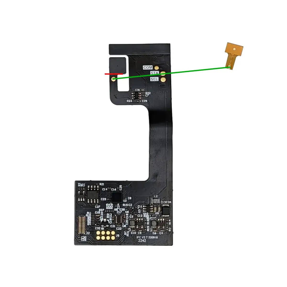
The touch sensor integrated into the ribbon cable is routed under the shell. If you use tape to secure the sensor, make sure it is as thin as possible so it doesn’t affect the sensor’s responsiveness.
The IPS kit comes with an additional touch sensor, which lets you place the touch sensor wherever you like. A popular spot for the sensor is, for example, under the IR cover. To do this, connect the external sensor to the “TCH” contact on the integrated touch sensor. The integrated sensor can then be cut off with scissors.
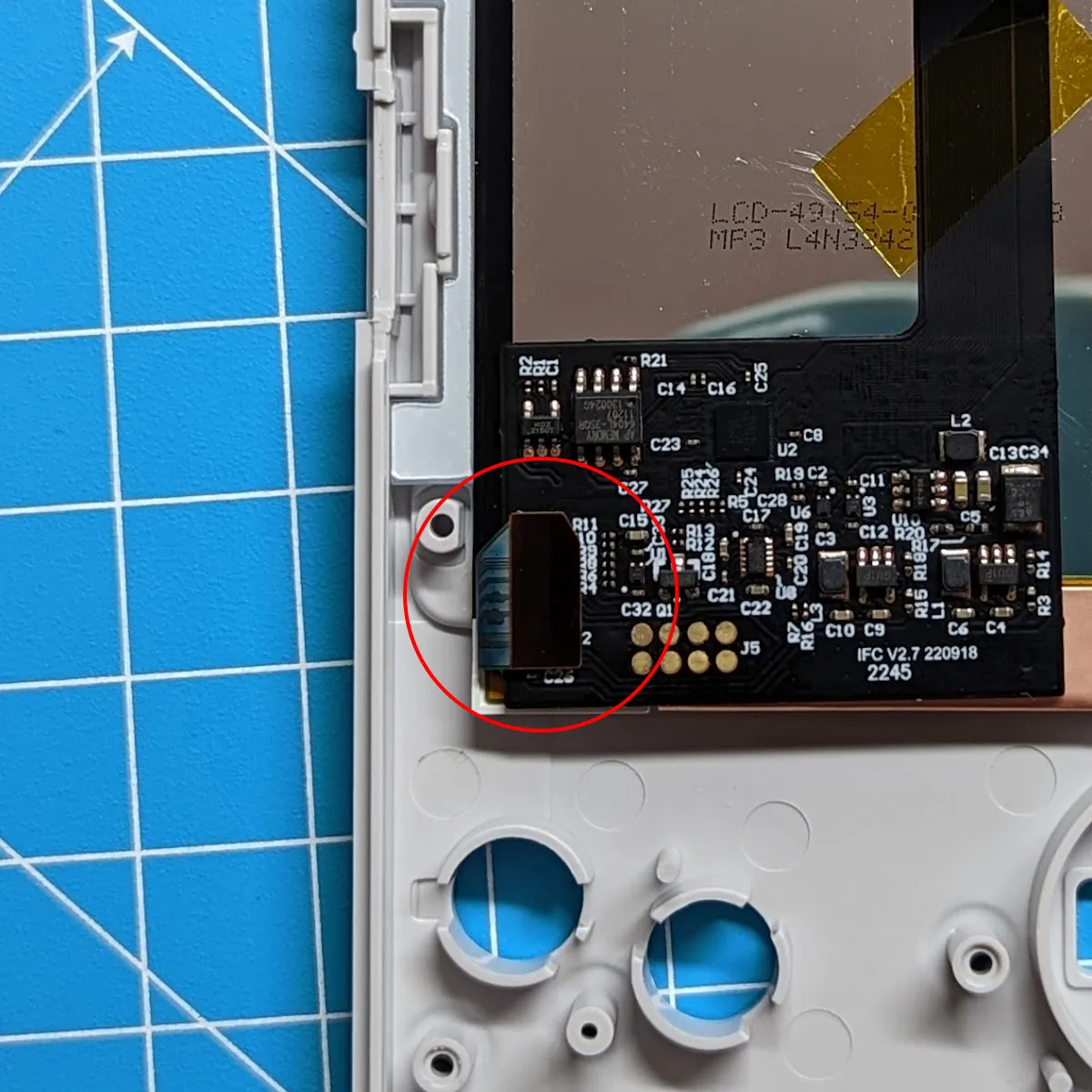
Usually the ribbon cable is already connected to the LCD on delivery. If not, attach the ribbon cable to the small connector at the bottom left of the LCD. Careful, do not put any pressure on the LCD!
To be able to control the kit with the buttons, the contacts on the ribbon cable have to be connected to the GBC mainboard.
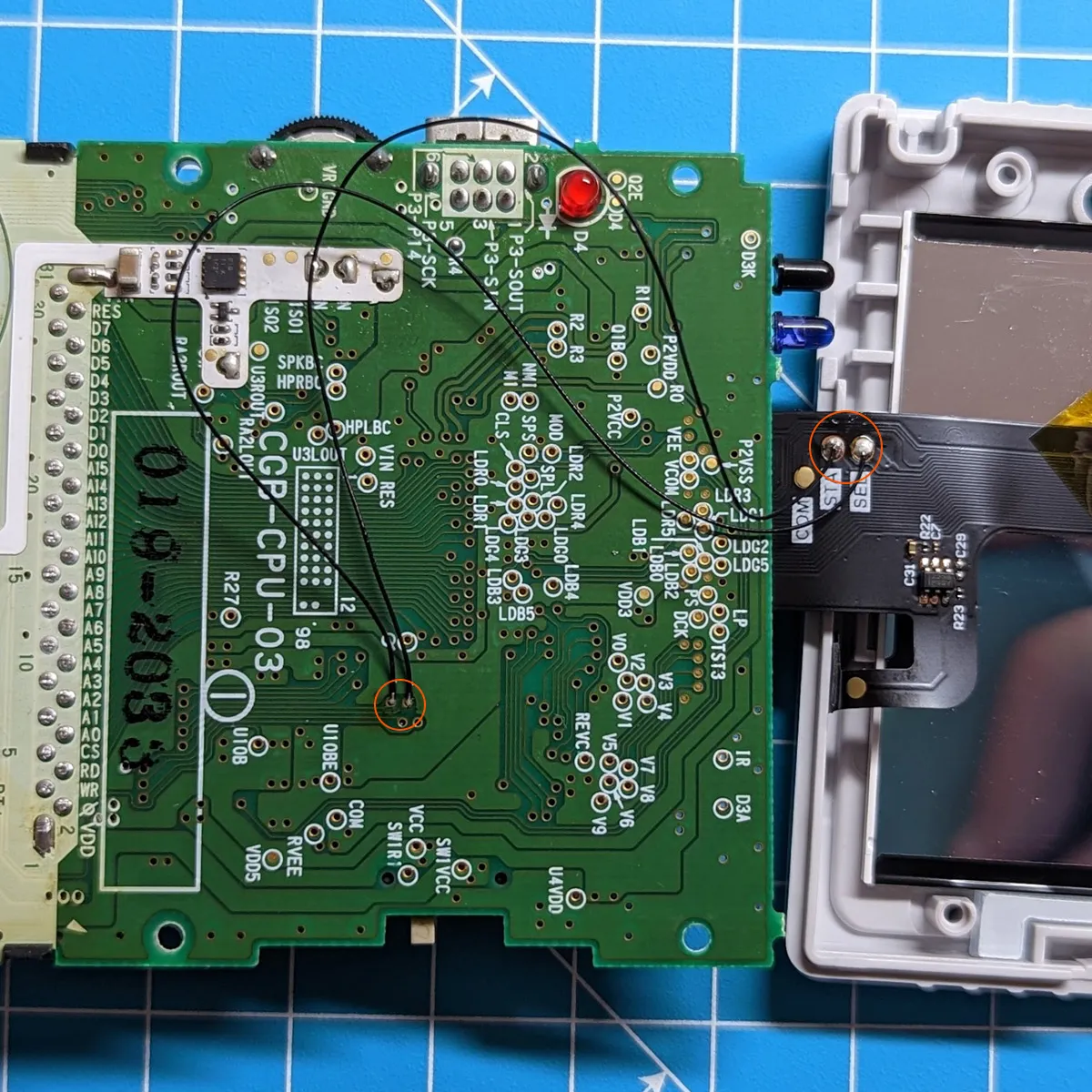
After a quick function test, insert the mainboard and screw it back in.
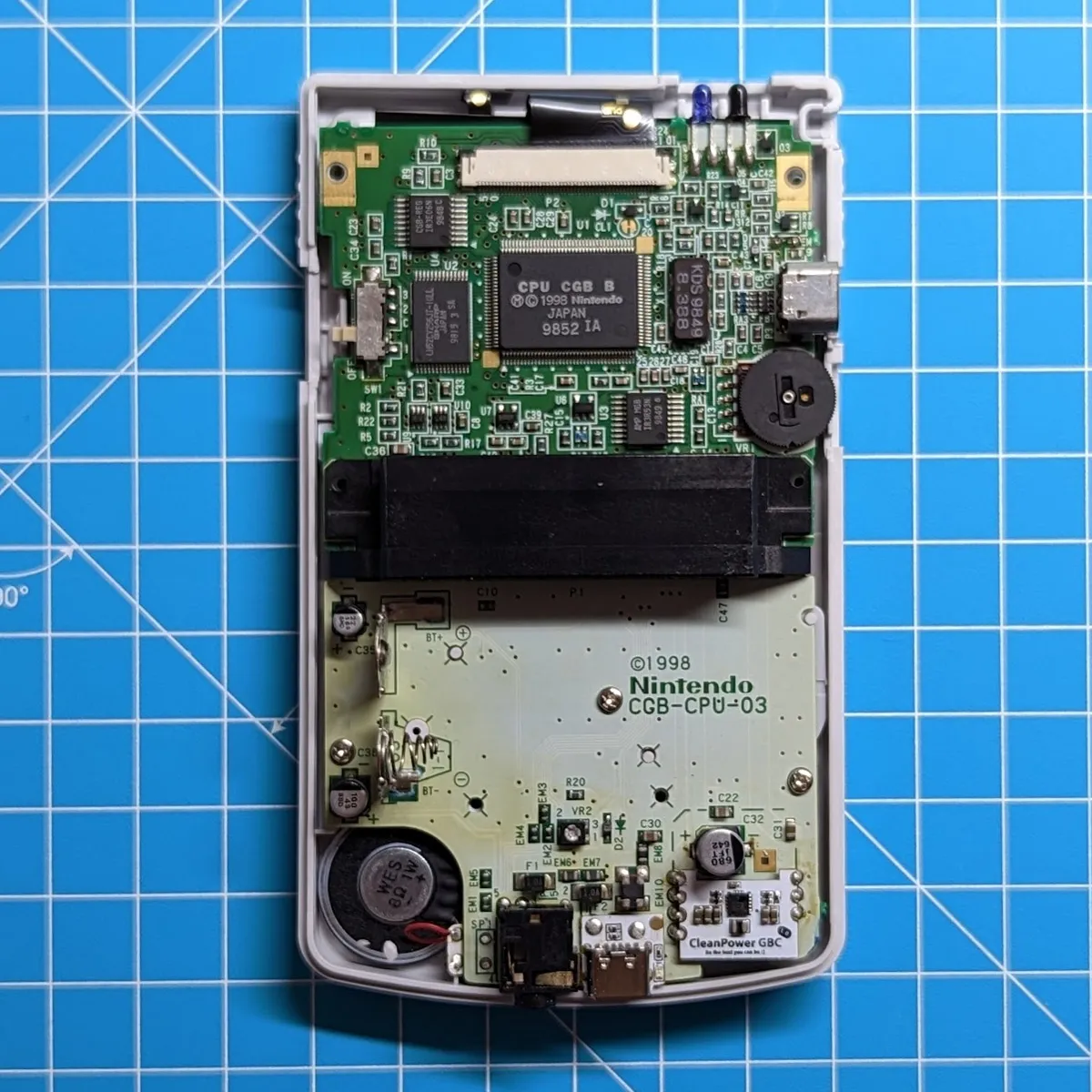
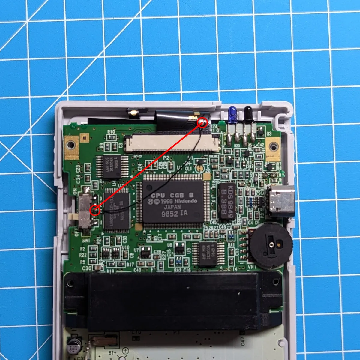
For power, run one more wire between PWR on the ribbon cable and the 3rd contact of the GBC power switch.
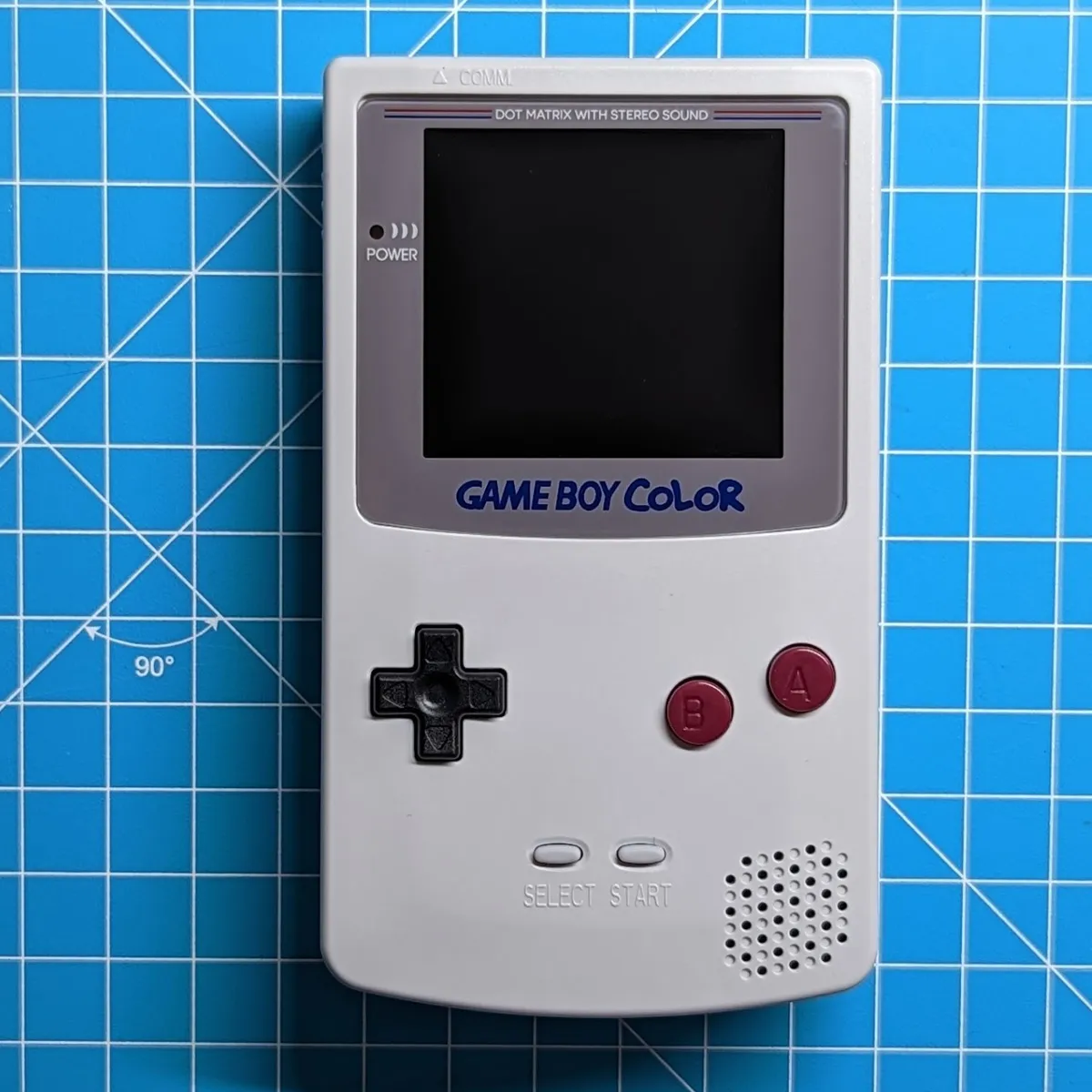
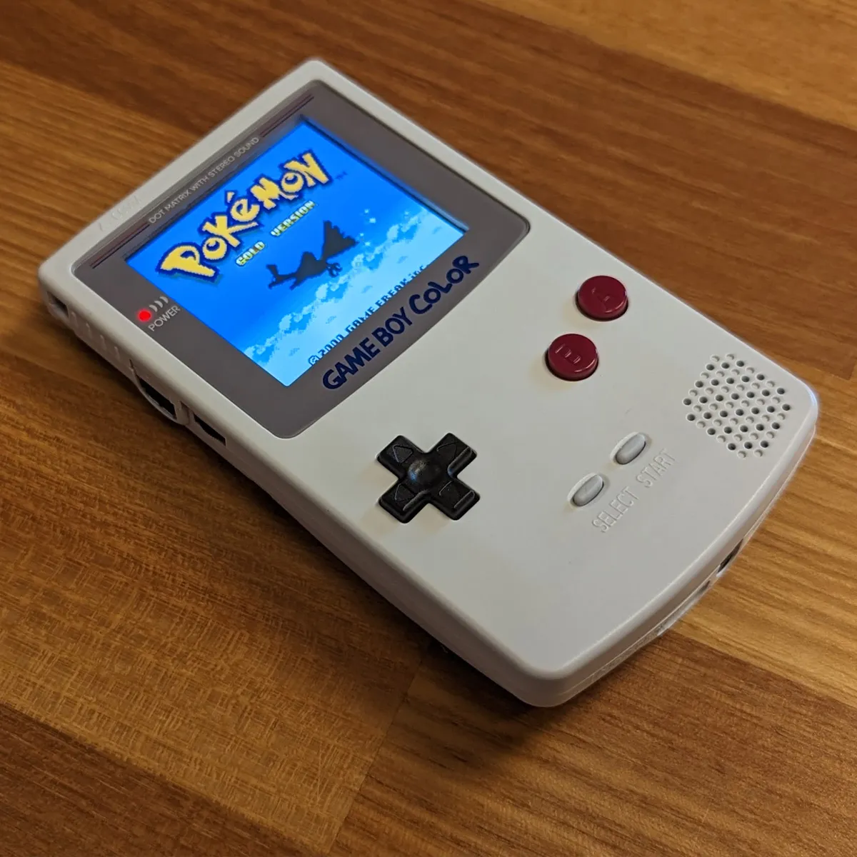
Finally, attach and screw on the back of the shell and install the display glass. To remove dust between the glass and the LCD, use an air blower.
Controls
Section titled “Controls”- Touch sensor short press: brightness control
- Touch sensor long press: RetroPixel effects
- Holding Start + Select activates configuration mode
In configuration mode, the touch sensor cycles through the options
- Option: Shift the image position vertically, Select moves it up, Start moves it down
- Option: Shift the image position horizontally, Select moves it right, Start moves it left
- Option: Change the logo lighting (only if the logo lighting has been installed)
Buy the RetroPixel 2.0 IPS Kit Backlite Mod for GBC at silentmodding.com