
[GBC] Installing the GBC IPS V3 by Hispeedido
The V3 IPS Kit by Hispeedido is one of the few kits that display the image at its original size. It combines the original look of the GBC with the benefits of a modern, vivid, high-contrast display. Thanks to the 2 touch sensors, the kit can be installed completely without soldering. Optionally, it can also be controlled via button combinations.
Foreword
Section titled “Foreword”- Make sure to run a function test , BEFORE you install the IPS kit! No warranty claims can be accepted for kits that have already been installed. You can see how to test the kit externally here: How do I test the LCD
- The LCD is very fragile and sensitive to pressure, impacts, etc. Please be especially careful when handling the LCD during installation
Preparation
Section titled “Preparation”The kit contains the following components
To open the shell you need
You can find suitable tool kits here
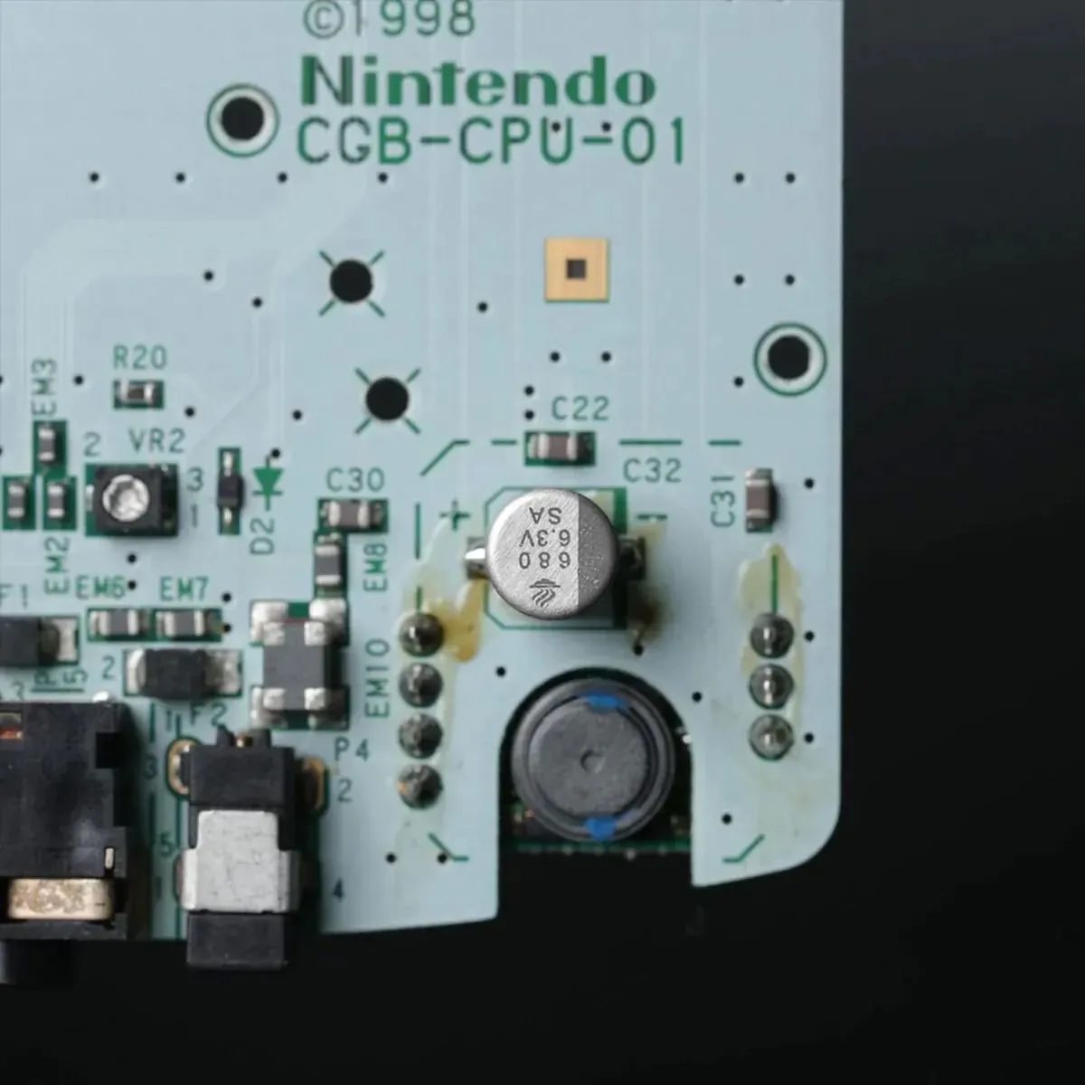
When doing an LCD mod, the 100uF capacitor should be replaced with a 680uF capacitor to reduce noise.
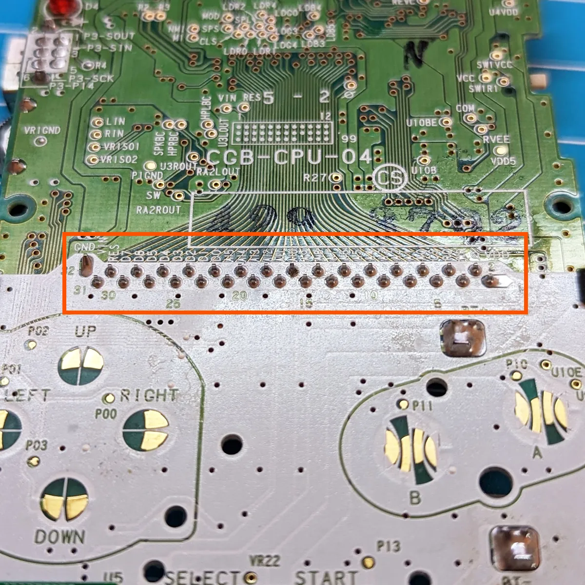
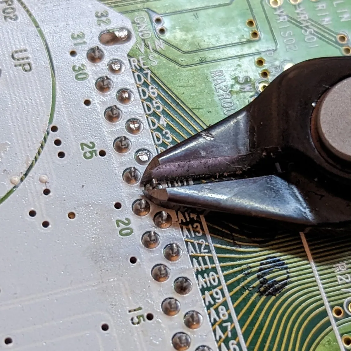
The pins of the cartridge port can press against the LCD, which can cause permanent damage. That’s why the pins have to be trimmed as short as possible with flush cutters. Watch out for flying pieces and protect your eyes!
Preparing the shell
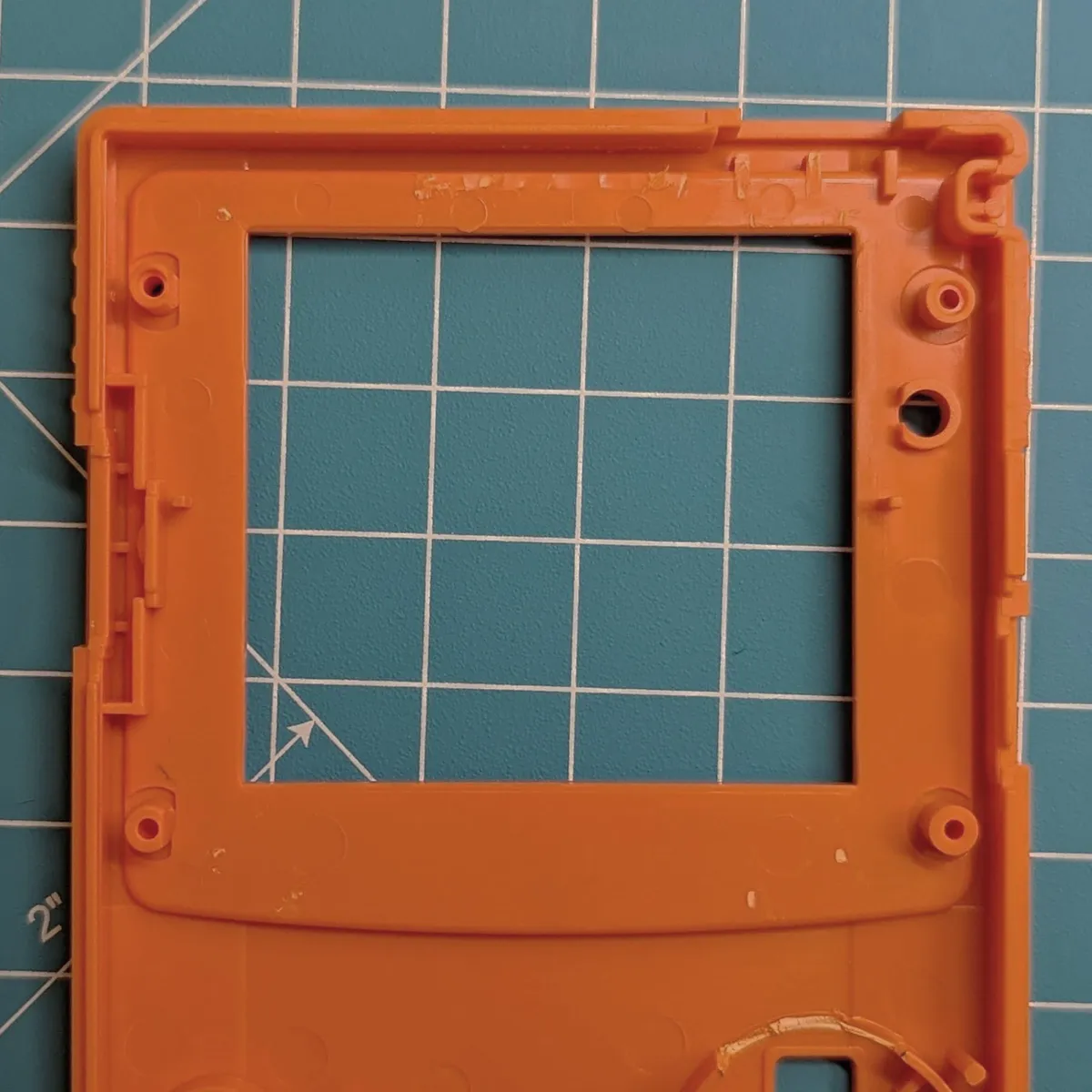
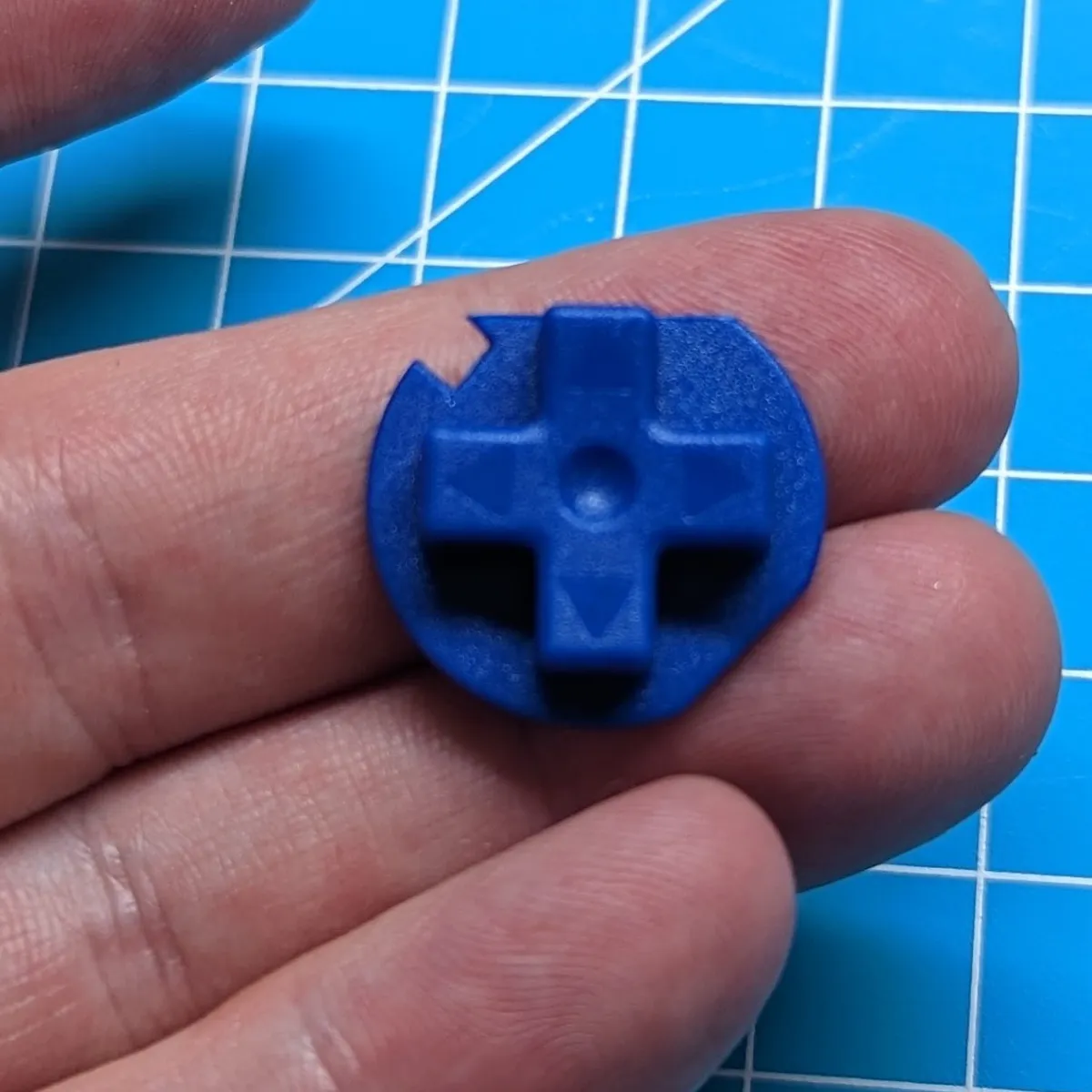
Section titled “Preparing the shell”To install the V3 kit, some modifications are needed so that the LCD fits into the shell. You can find a guide for OEM shells here, for RetroSix shells here
Installation
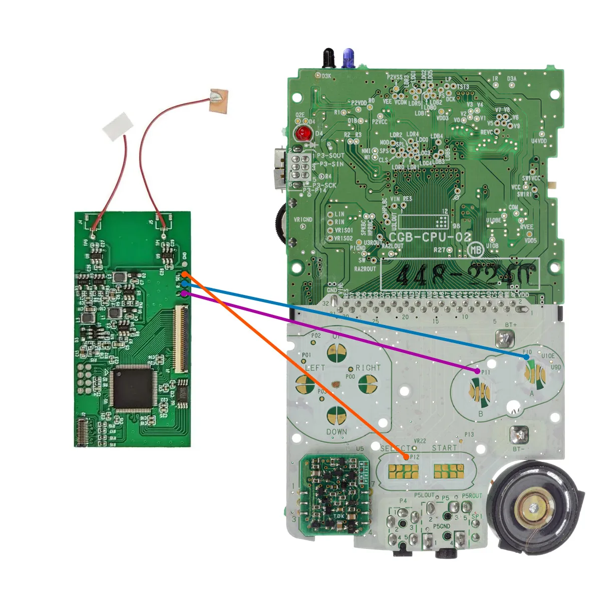
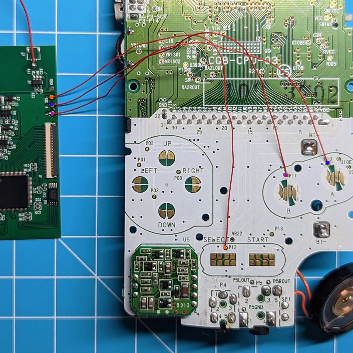
Section titled “Installation”Optional: The V3 can also be controlled with button combinations. To do this, connect the respective contacts for START, A and B to the corresponding contacts on the GBC mainboard.
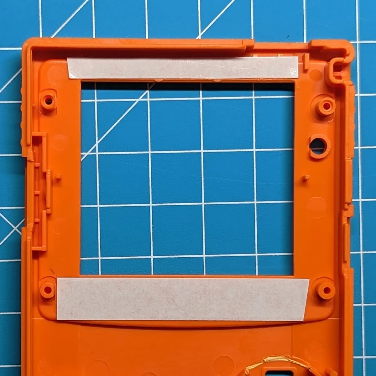
Using the included adhesive tape, apply one strip above and one strip below the display opening.
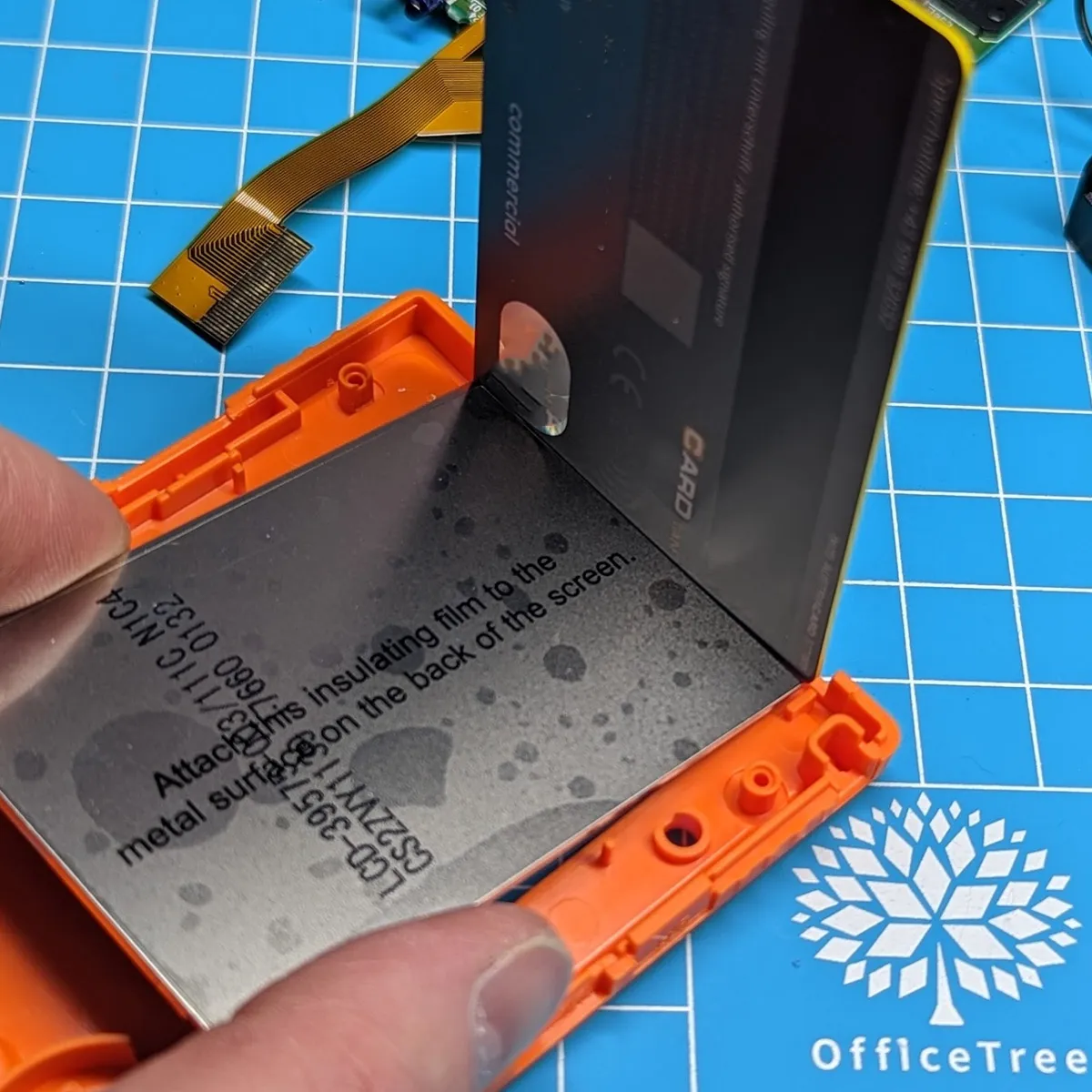
Stick the large insulation film onto the back of the LCD to prevent short circuits later on. Glue the LCD exactly centered into the shell, aligning it at the top with the upper edge of the shell. Depending on the display lens you use, you may need to leave a little gap at the top. Inserting a card can help you keep the gap at the top even.
Once the display is stuck in position, connect the LCD to the PCB via the small connector. Caution: Do not apply any pressure!
You can use a leftover adhesive strip to attach the PCB to the back of the LCD. The touch sensors are stuck to the underside of the upper edge of the shell.
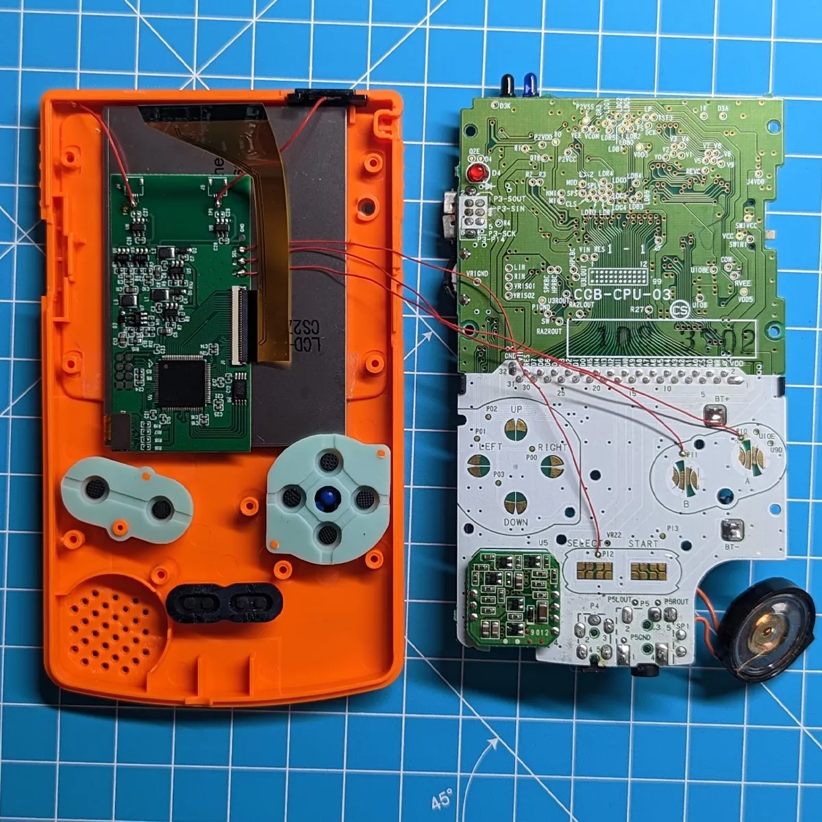
After inserting the buttons and pads, connect the PCB’s ribbon cable to the connector on the GBC mainboard and secure the mainboard with 3 screws.
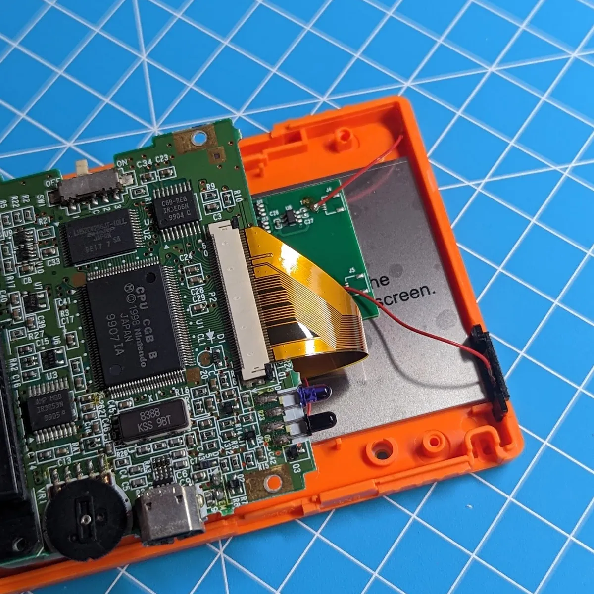
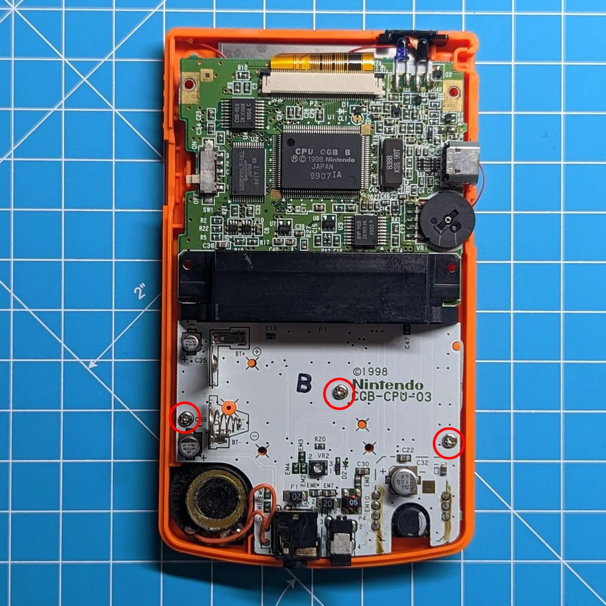
Finally, attach and screw on the back of the shell and stick on the display lens. To avoid trapping dust between the LCD and the display lens, an air blower comes in handy.
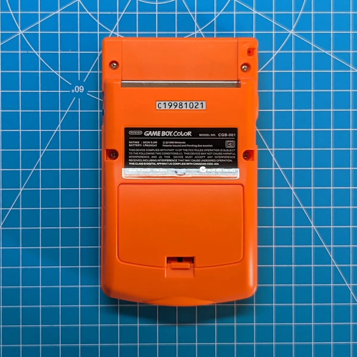
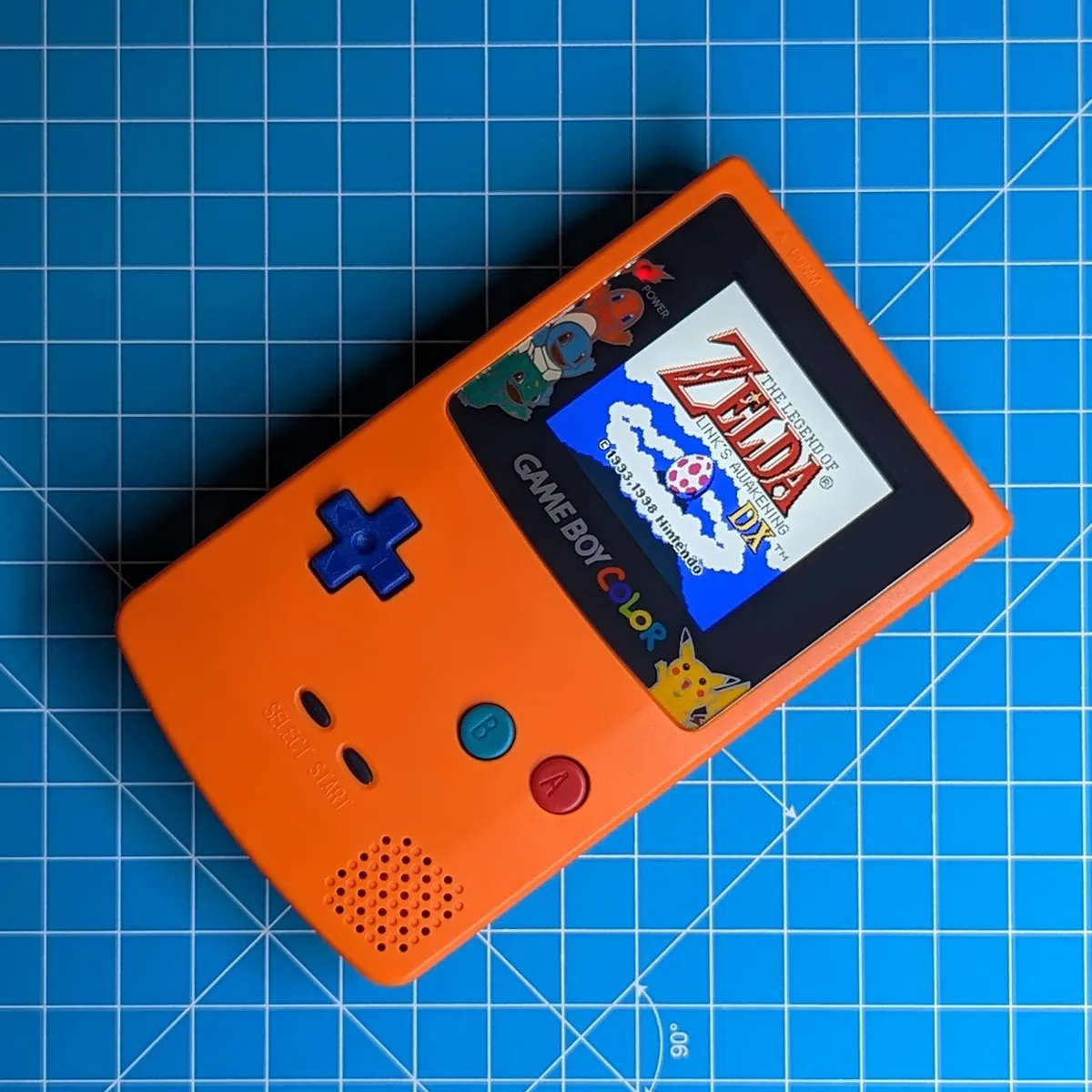
Touch controls
Section titled “Touch controls”- Left touch sensor: change color palette
- Right touch sensor: brightness control in 10 steps
Button controls
Section titled “Button controls”- SELECT + A
- SELECT + B
- Holding START + A + B cycles through the color palettes at 1-second intervals
Buy the GBC IPS BackLite Mod Kit V3 by Hispeedido at silentmodding.com