
[GBC] Hispeedido 2.45 OSD IPS Kit
This is the install guide for the Hispeedido GBC 2.45” drop-in IPS LCD backlight kit with OSD.
Warnings
Section titled “Warnings”- Test before installation! When you receive a backlight/LCD kit, do a dry run before installing it to make sure nothing was damaged in transit. See How do I test the LCD for how to do it. During a dry run the kit is not installed in the shell: no adhesives, no brackets, no soldering. All ribbon cables must be free of bends or creases. Kits that have been installed are not eligible for replacement or return.
- The LCD may break if it’s put under too much pressure or dropped. Be extremely careful during installation.
- The console or LCD can be damaged if you don’t trim the cartridge slot pins. Be careful when trimming them and wear eye protection, as bits of metal can fly off. Flush cutters work well for this. Damage caused by these pins is not covered by return or exchange. Trim the pins of the cartridge slot flat so they don’t touch any part of the kit. We also recommend putting some Kapton tape over the trimmed pins to prevent shorts.
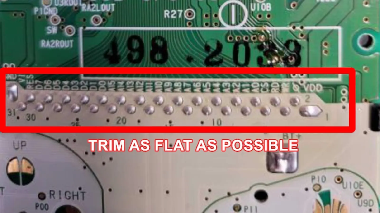
According to our product description, the kit fits OEM shells and most IPS-ready shells without modification. If your shell still needs some work, see GBC shell trimming.
Install guide
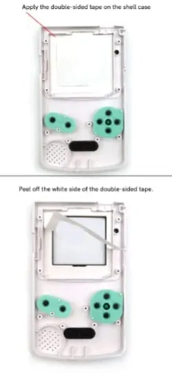
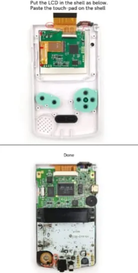
Section titled “Install guide”The steps are shown directly in Hispeedido’s images:
- Apply the double-sided tape on the shell.
- Peel off the white side of the double-sided tape.
- Put the LCD in the shell as shown.
- Stick the touch pad onto the shell.
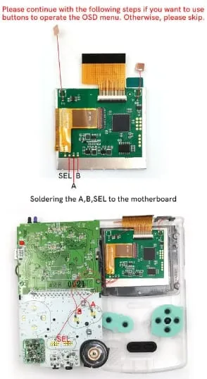
- Optional: if you want to use the buttons to operate the OSD menu, solder A, B and SEL to the main board. Otherwise, skip this step.
Using the touch sensors
Section titled “Using the touch sensors”The kit comes with two pre-installed touch sensors, so you can operate the OSD menu without soldering:
- Touch both touch sensors for 5 seconds to open the OSD menu.
- Touch the left touch sensor to select a menu item.
- Touch the right touch sensor to change the selected setting.
If you prefer to control the menu with the buttons, solder the included wires as shown in step 5.
Troubleshooting
Section titled “Troubleshooting”- IPS Troubleshooting (Hand Held Legend)