
[GBA] FunnyPlaying ITA TFT Kit
Video guide
Section titled “Video guide”Getting started
Section titled “Getting started”Required tools and parts
Section titled “Required tools and parts”- Tweezers
- J1 (Japanese Industrial Standard) screwdriver
- Y1 tri-point screwdriver
- A GBA shell modified for the ITA kit (see Modify the shell)
Take inventory
Section titled “Take inventory”Make sure you have all the parts included with the kit:
Before you proceed:
- Fully disassemble your Game Boy Advance: Disassembly Guide (GBA Original) (Hand Held Legend)
- Find out whether you have a 32 pin or 40 pin GBA: GBA 32 pin or 40 pin?
- Fully dry test your kit before installation: How do I test the LCD
Install guide
Section titled “Install guide”Choose your ribbon
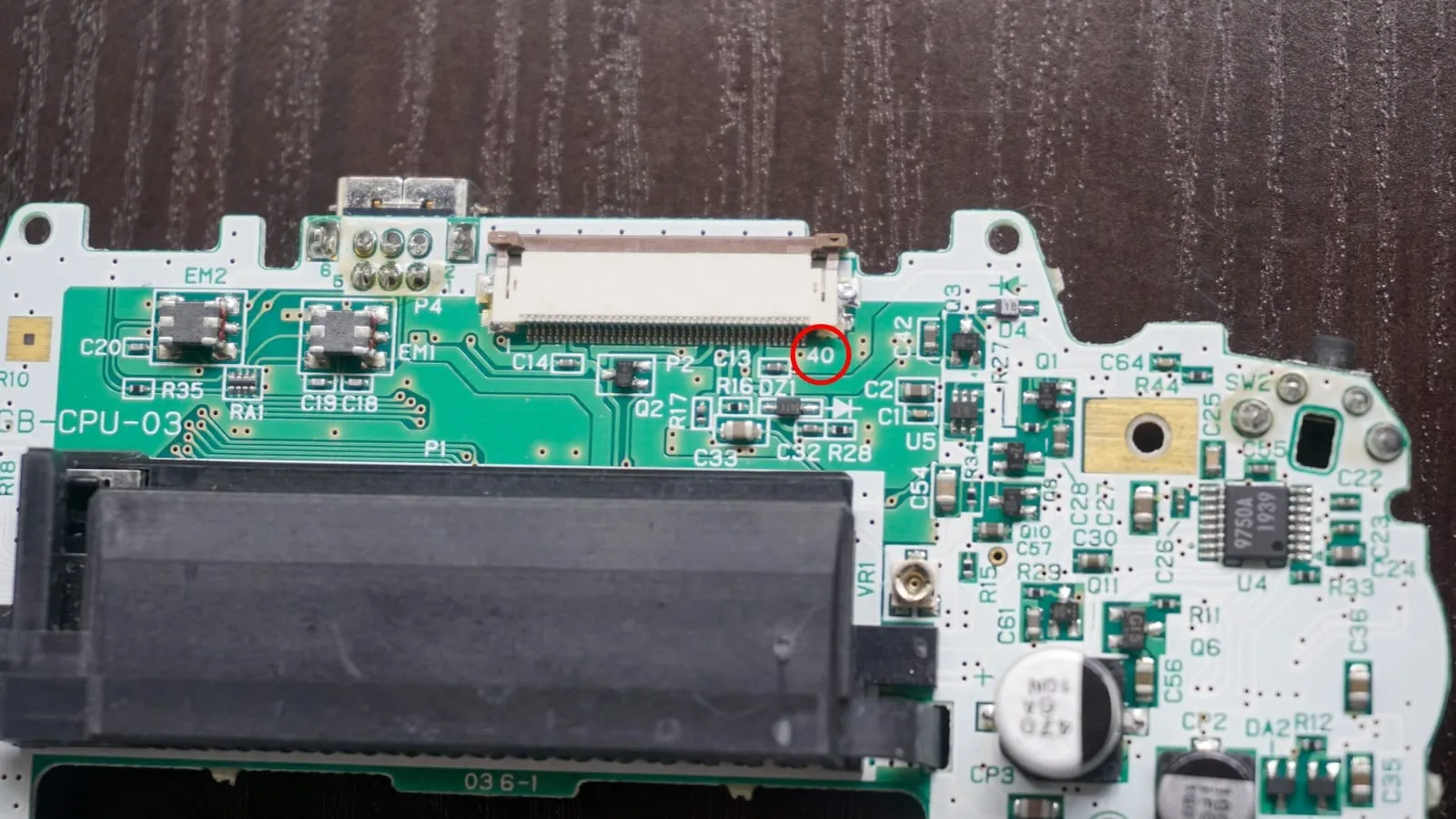
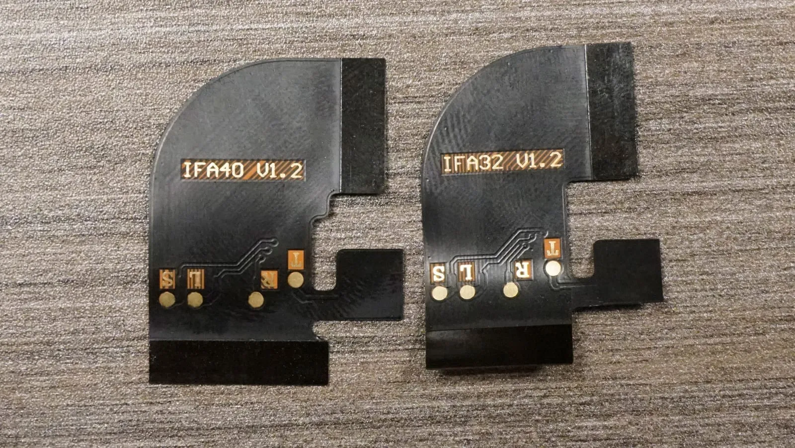
Section titled “Choose your ribbon”Look at the main board to determine which of the included flex cables (FPC) you need. There is a 32 pin and a 40 pin option.
Dry testing
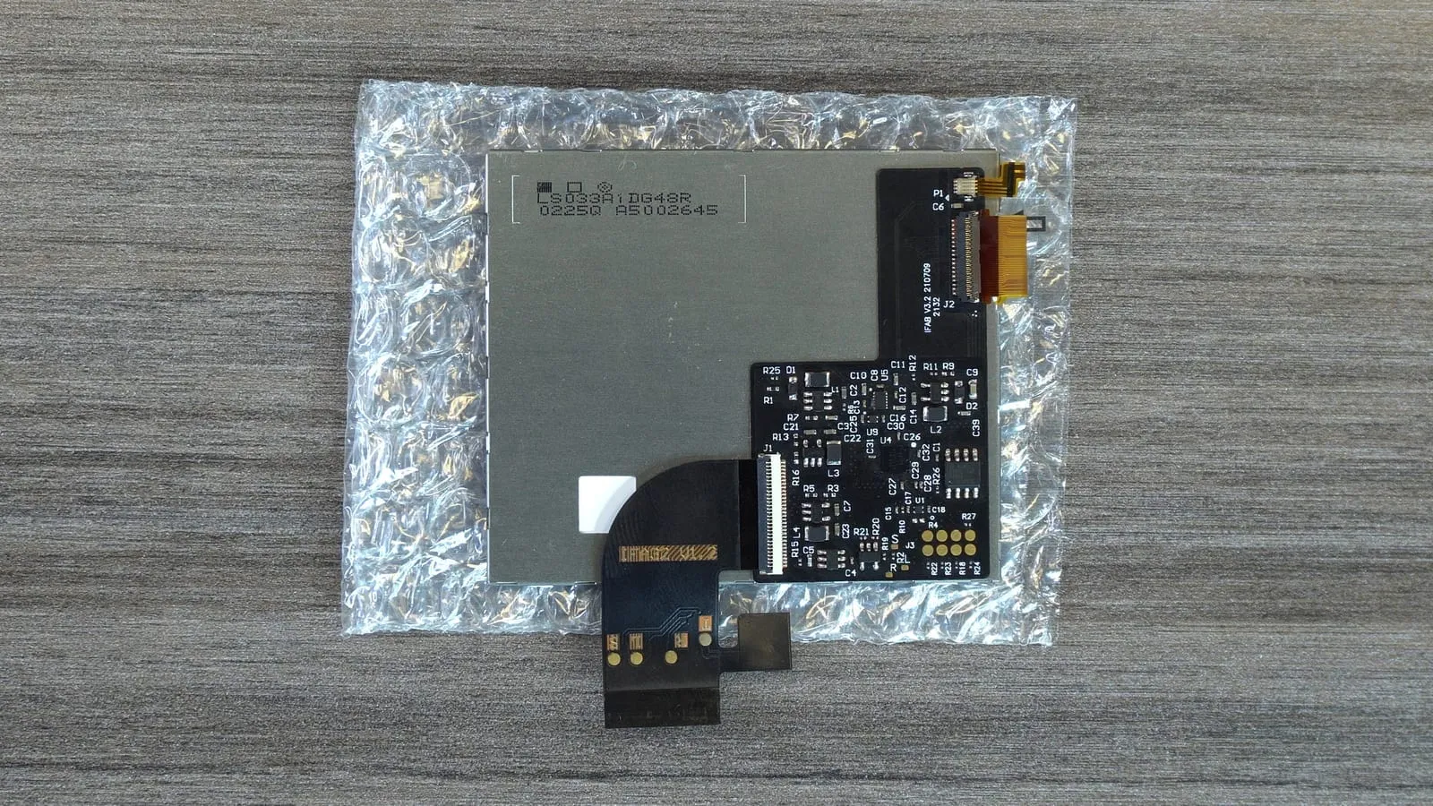
Section titled “Dry testing”Connect the matching ribbon cable to the TFT board with the gold contacts facing down. Close the connector latch with your fingernail or a plastic spudger.
Connect the other end of the flex cable to the console’s main board and close the latch there as well.
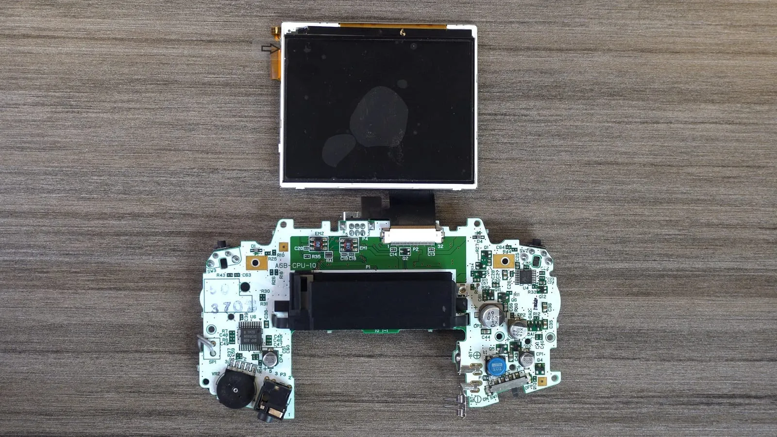
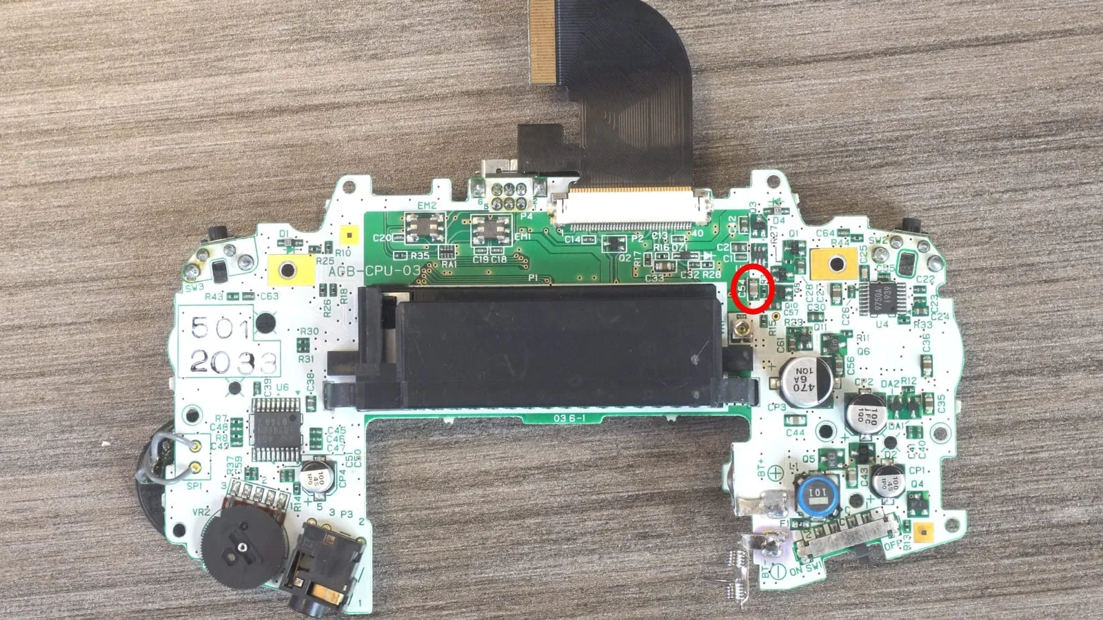
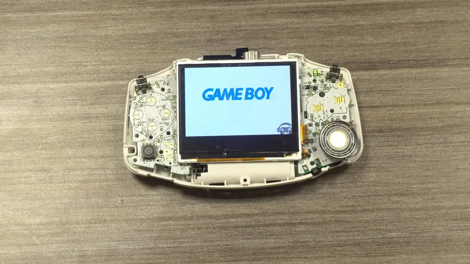
Place the main board into the rear housing. Carefully flip the panel over the board. Insert two AA batteries and turn the power switch on. The screen should power on. For more details on dry testing, see How do I test the LCD.
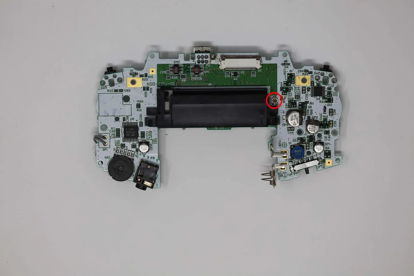
On some consoles you may have to adjust the potentiometer to get the screen working properly. Only make small adjustments until the picture looks normal.
Modify the shell
Section titled “Modify the shell”The shell of the Game Boy Advance has to be modified to make room for the TFT display. How much you need to cut depends on the shell you use.
TFT-ready shells
Section titled “TFT-ready shells”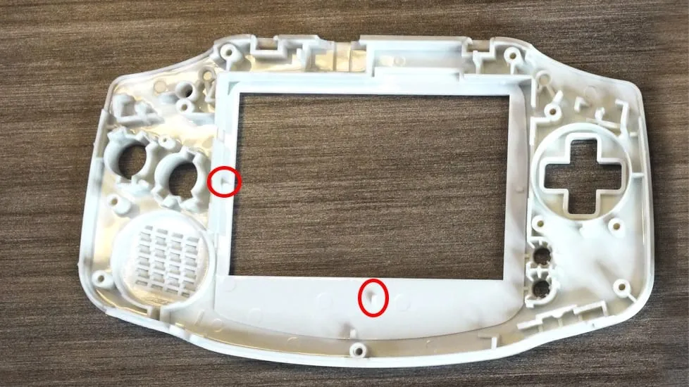
Even with a TFT-compatible shell, we still recommend removing these two plastic tabs with flush cutters.
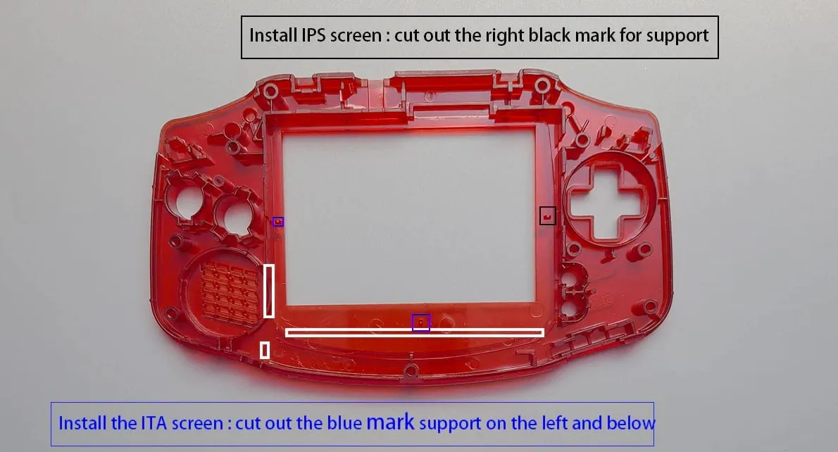
FunnyPlaying ITA/IPS shell
Section titled “FunnyPlaying ITA/IPS shell”The image below from FunnyPlaying shows where to cut the FunnyPlaying ITA/IPS shell when installing the ITA TFT kit (or a GBA IPS kit without a bracket):
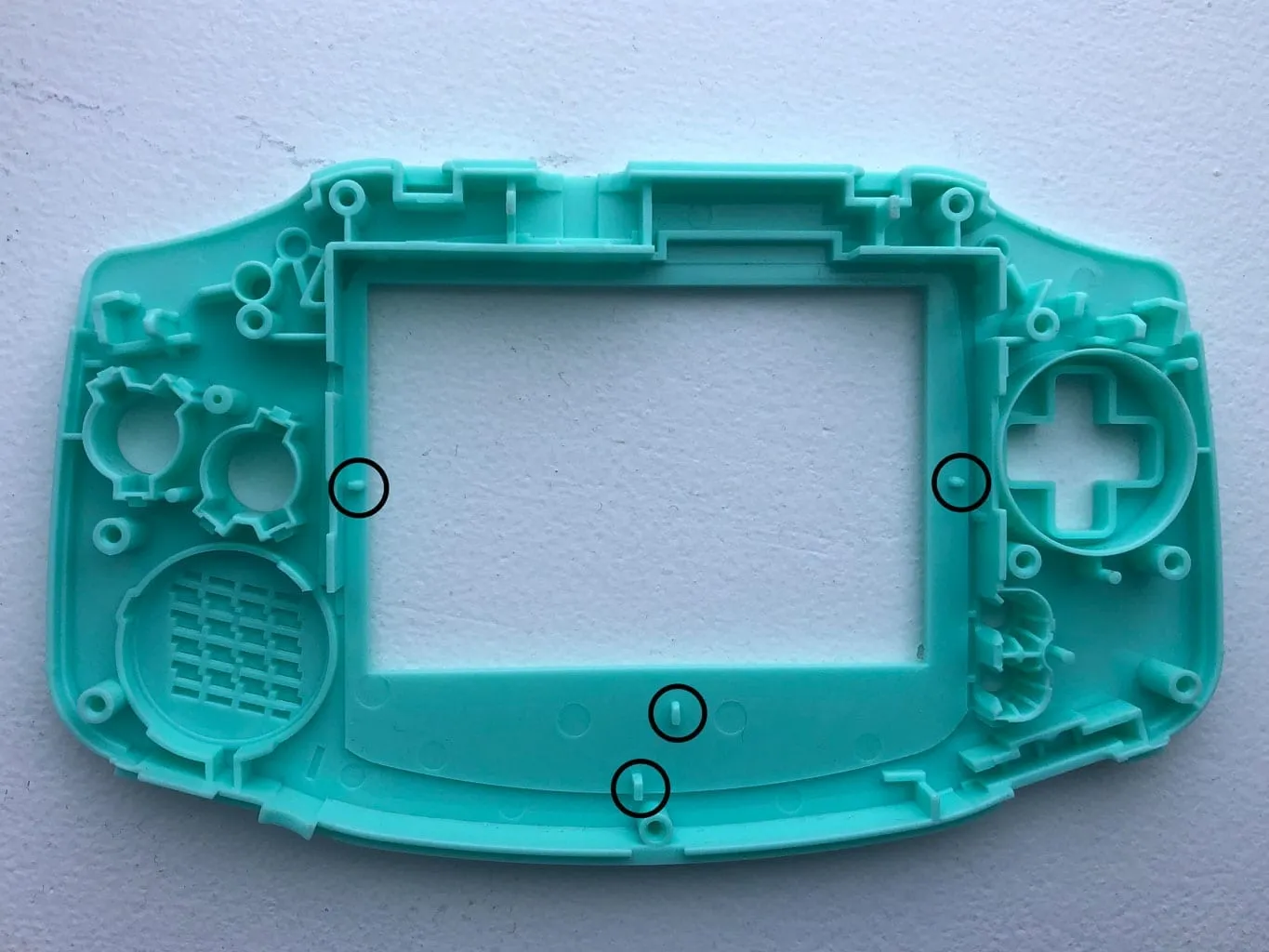
If you use this shell with a GBA IPS kit and a V2 or V3 bracket instead, cut the areas circled below:
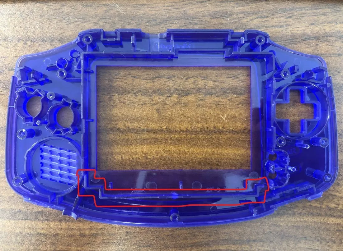
Afterwards, smooth out the cuts with sandpaper so the display doesn’t get damaged during installation.
OEM shells
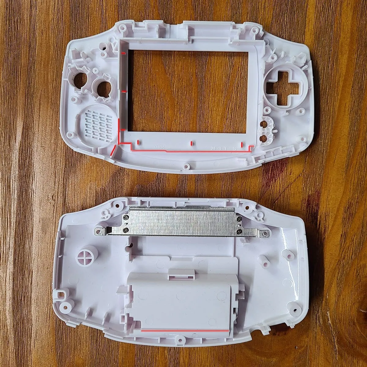
Section titled “OEM shells”Original shells need a lot more work. You have to cut out everything marked in red to fit the new screen.
More trimming guides are available from Hand Held Legend (OEM Non-IPS GBA Shells Trim Guide) and, for RetroSix shells, in our guide GBA RetroSix shell trimming.
Modify the screen
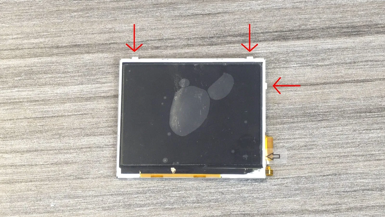
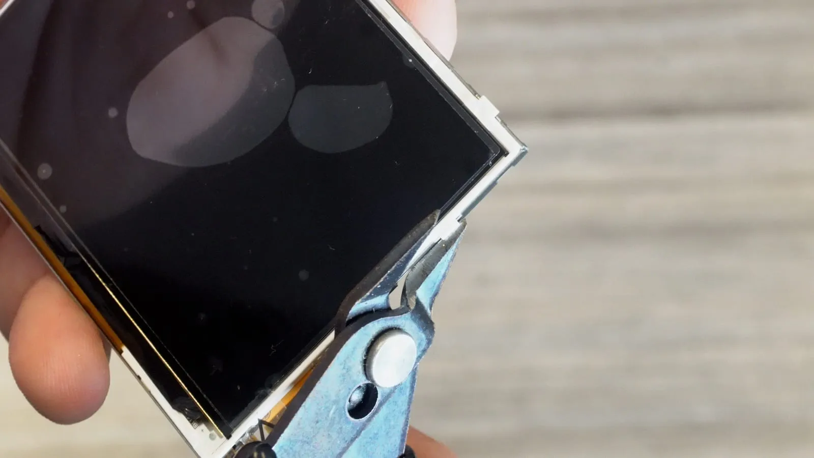
Section titled “Modify the screen”The screen has three white tabs that have to be removed before final installation. A craft knife or a pair of flush cutters works best.
Solder the ribbon cable
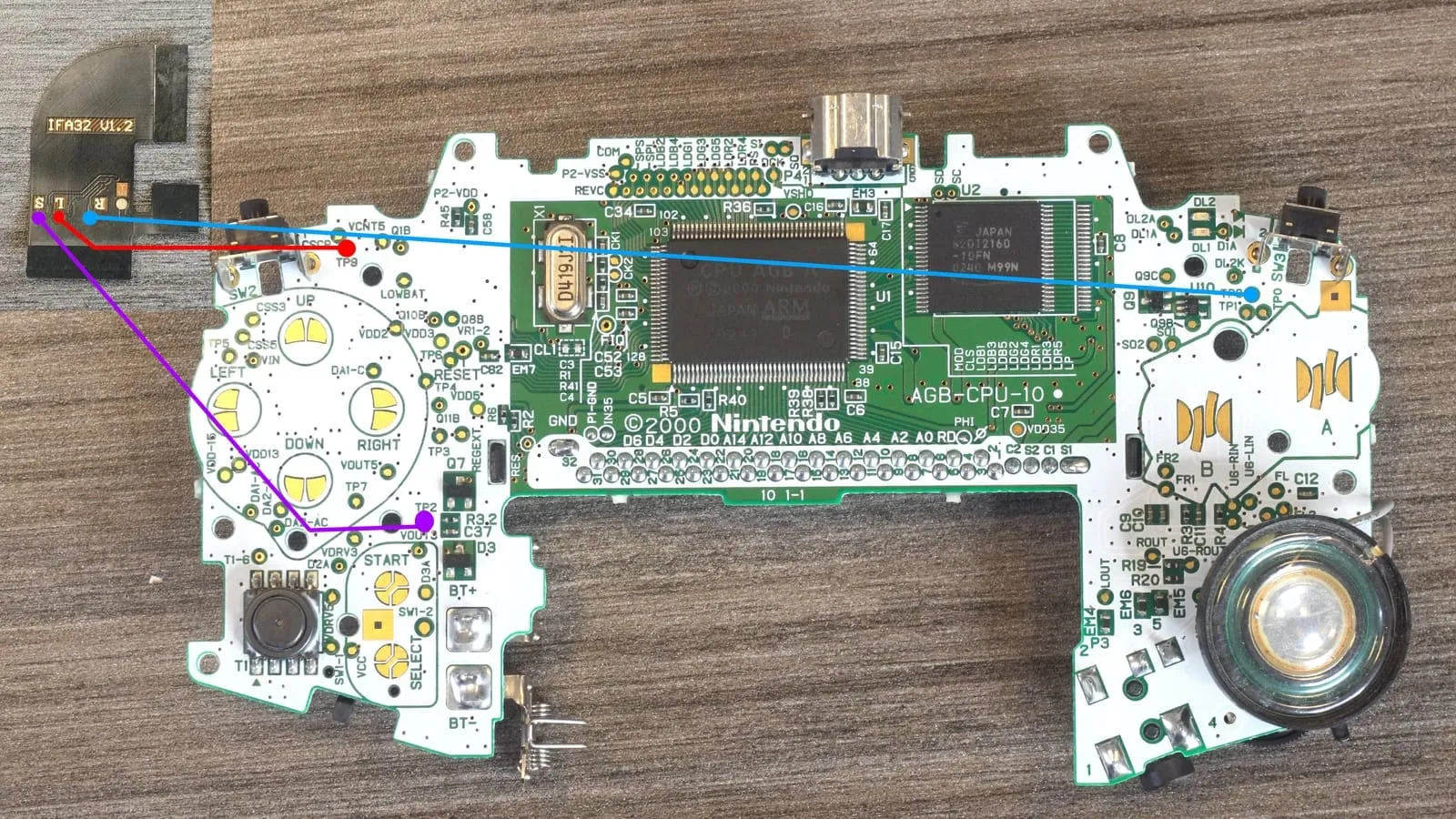
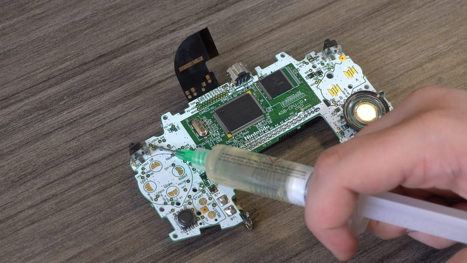
Section titled “Solder the ribbon cable”Solder the pads on the ribbon cable to the main board as shown below. For this mod you need Right, Left and Select. Optionally, you can also solder the touch sensor to relocate it.
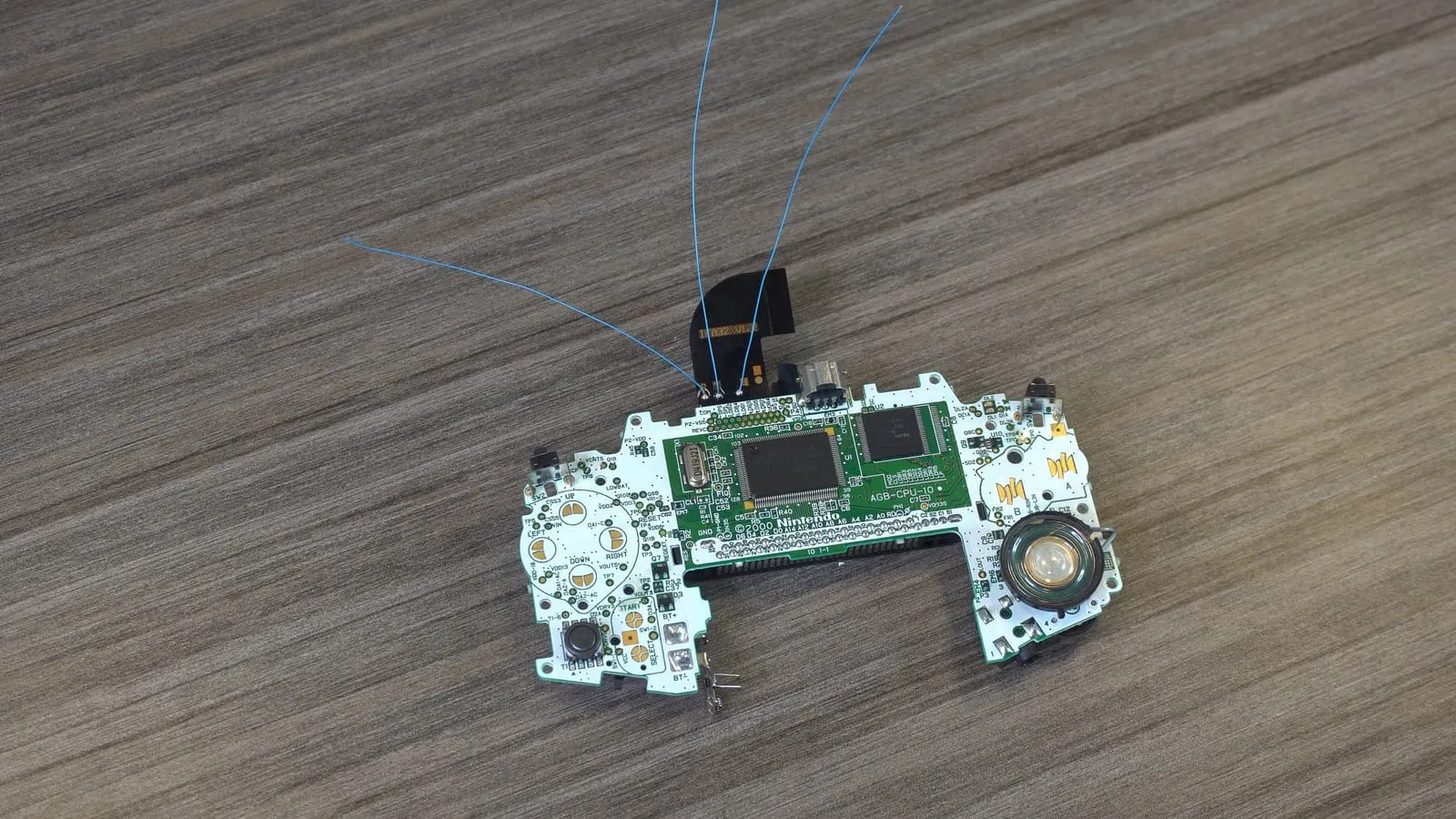
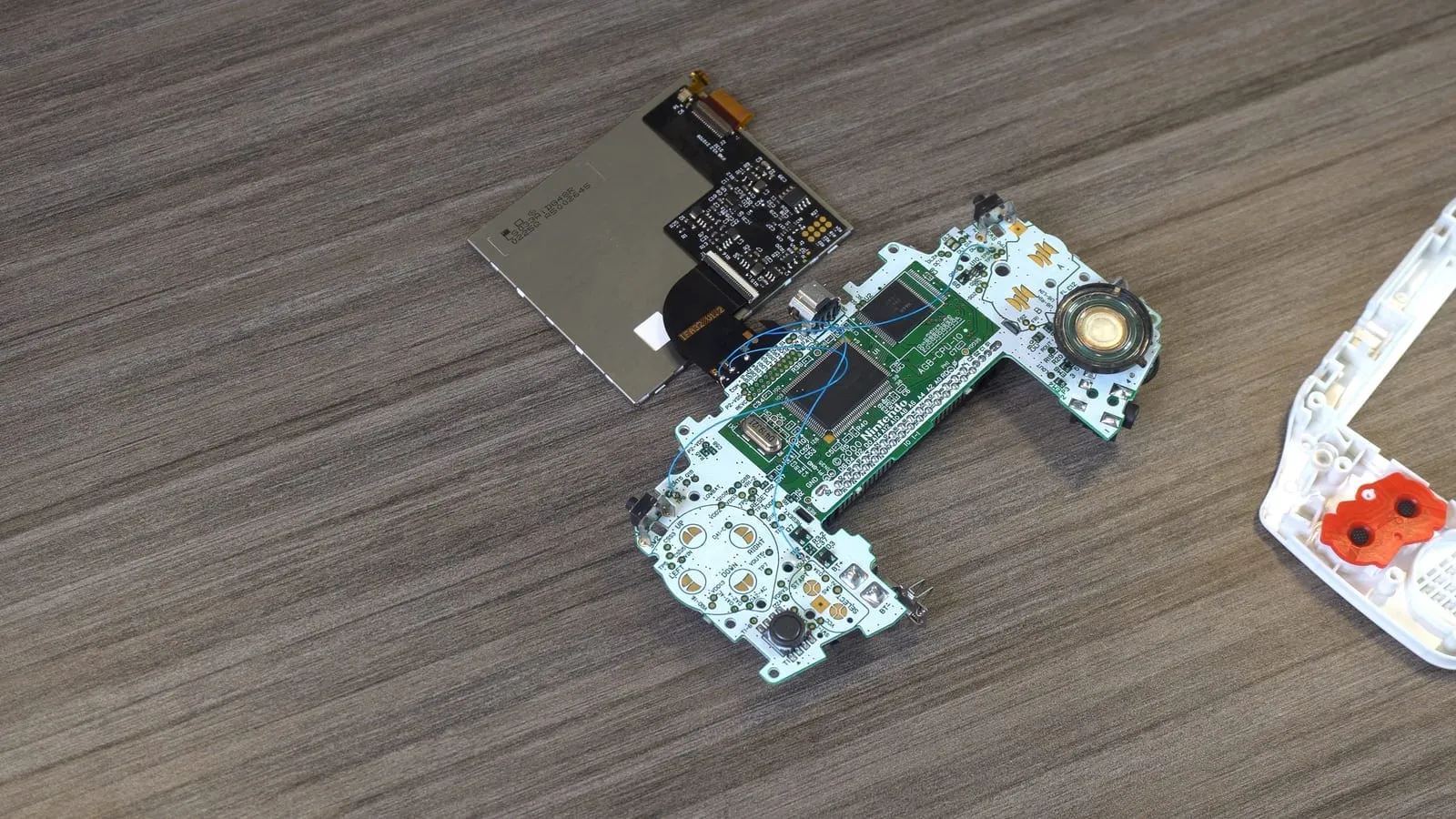
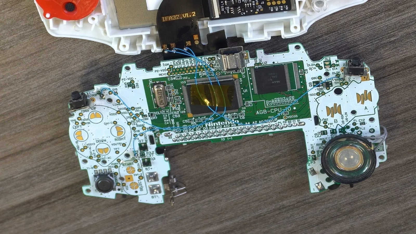
Test and reassemble
Section titled “Test and reassemble”To prevent shorts on the TFT controller board, cover it with the protective film that came on the screen. Don’t screw anything together yet. Insert batteries and power the console on. The display should light up. If it doesn’t work as expected, carefully inspect all connections and try again. You can adjust the brightness by holding Select and pressing L or R.
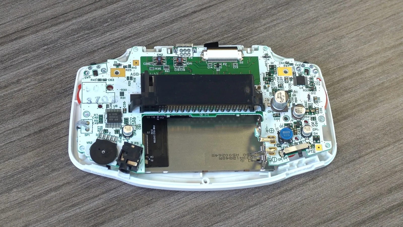
If everything works, you can reassemble the console. Insert all face buttons, the LED lens and the button membranes. You can also put the side pieces back on.
Note that the display has to sit in the top left of the screen window, as shown below.
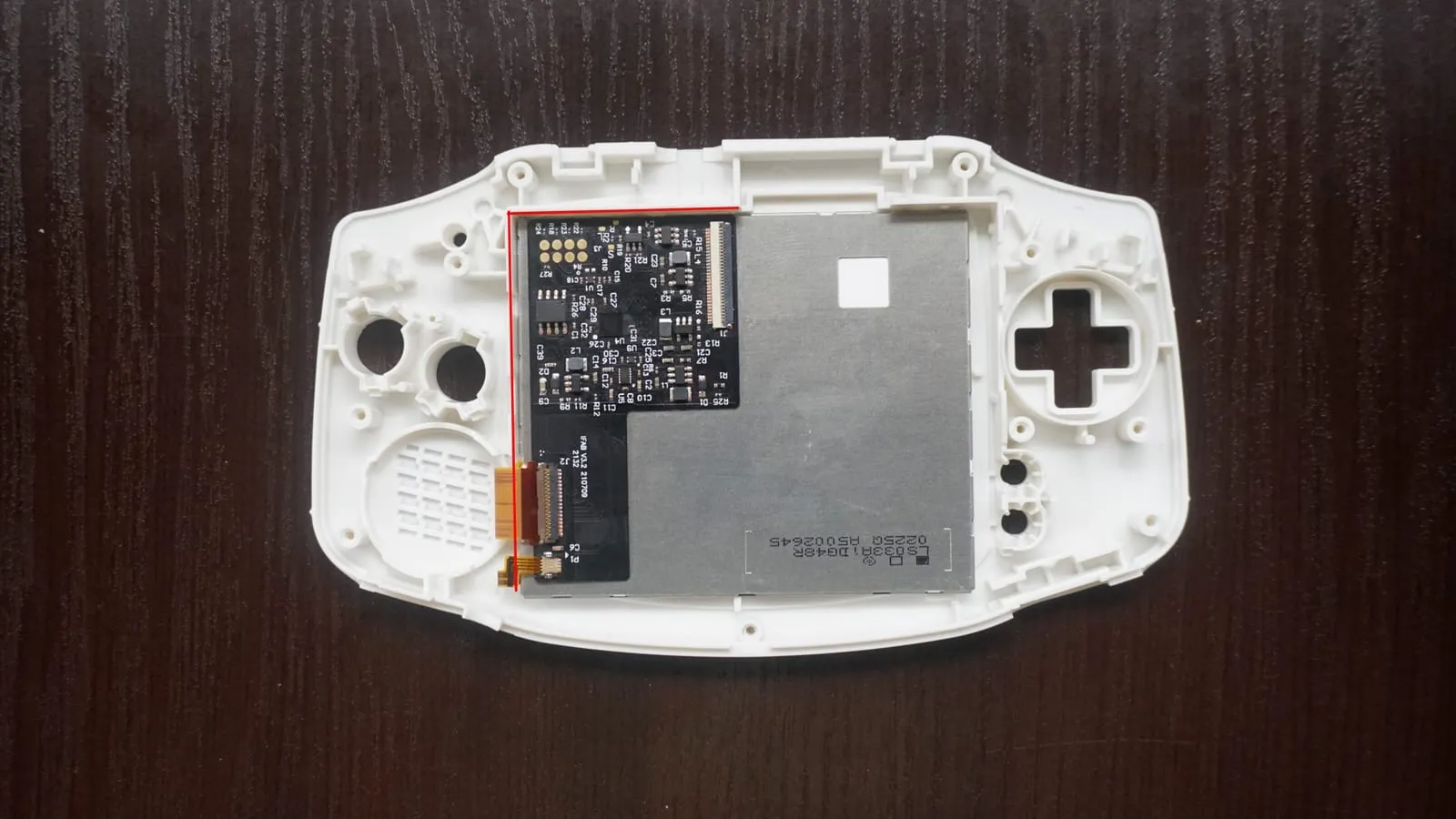
Place the main board into the front housing and make sure the speaker lines up with its cutout. Install the 3 J1 screws to secure the main board. From here you can finish reassembling the console.
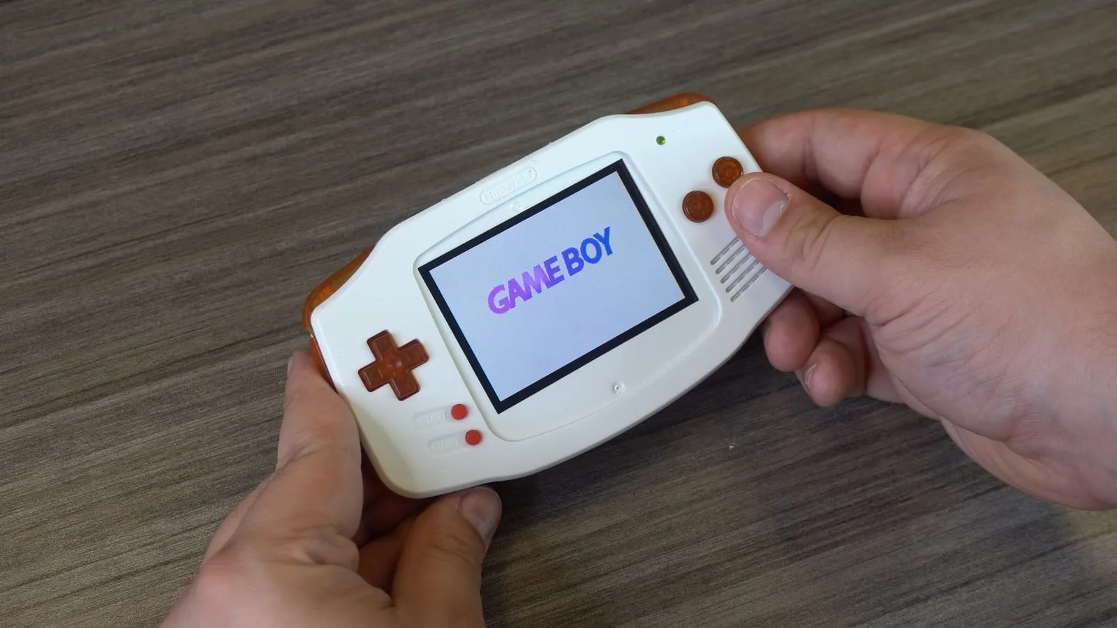
If everything works as expected, finish by replacing the rear screws. See the Disassembly Guide (GBA Original) if you need help.
Troubleshooting
Section titled “Troubleshooting”- IPS Troubleshooting (Hand Held Legend)