
RetroSix CleanRGB Universal
The CleanRGB Universal can be installed in any console that has native RGB signals somewhere on the board.
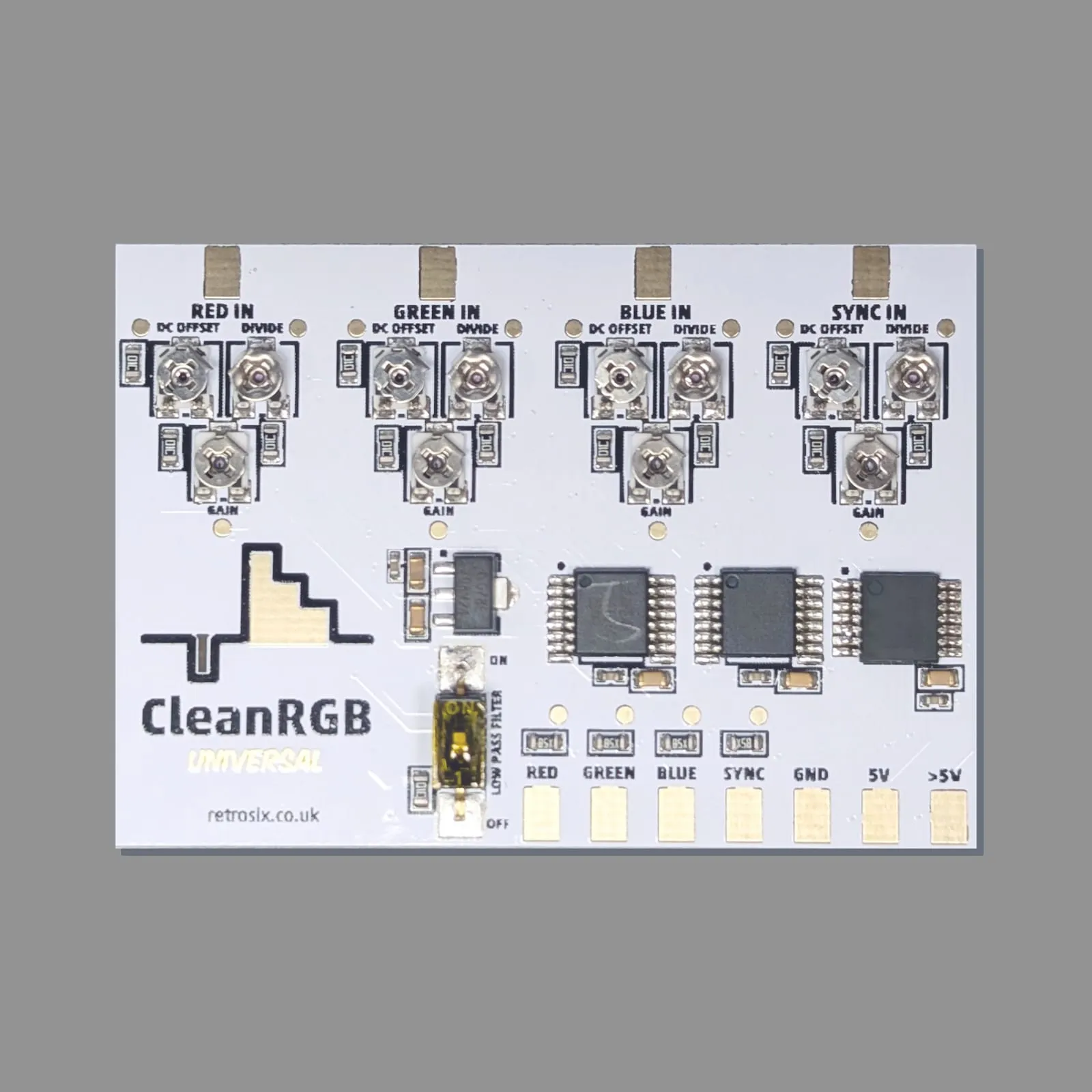
The CleanRGB tunes those signals to correct IRE levels: it removes the DC offset, cleans and filters the signal and sets the gain correctly.
Basic installation
Section titled “Basic installation”Solder the CleanRGB to ground and 5V (or, if the voltage is above 5V, to the >5V pad). Then connect the RGB and Sync inputs to your source signals and the outputs to the AV port.
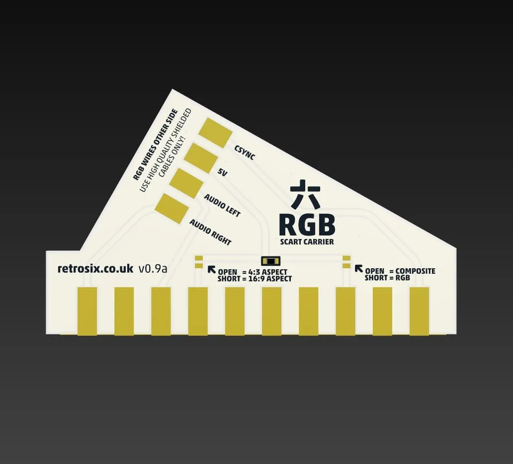
The output works with most RGB cables. RetroSix tests and recommends its own Pure DC CleanRGB SCART cables. They have no magic inside: no capacitors, resistors, sync strippers or other parts, just good old shielded, high-quality pin-to-pin connections.
Install guides for specific consoles follow further down.
DC-coupled RGB
Section titled “DC-coupled RGB”All RetroSix RGB mods are DC-coupled, while most others are AC-coupled. The reason is simple: AC coupling was only ever there to protect the NPN transistors in old equipment in case the RGB lines were accidentally shorted to ground, which would burn out the transistors in the display’s input stage.
Today almost everyone plugs their RGB cables into modern capture cards, upscalers or CRTs/PVMs with short-circuit protection on the input stage (only really old ones had none). Adding capacitors to the lines is often just copied because others do it. This article explains it well: To AC-Couple or Not to AC-Couple.
AC coupling has many disadvantages (higher cost, field tilt, droop, capacitive double coupling and more) and only one advantage: it protects really old CRTs in case someone shorts the cable to ground.
That’s why the RetroSix CleanRGB SCART cables pass pure RGB and Sync from the console to the TV. No custom resistors, no current shunting to lower the levels, no capacitors to remove DC bias. The CleanRGB mods inside the consoles correct these flaws, and the cable does just what it should: patch the console’s AV port through to the SCART pins.
Tuning by eye
Section titled “Tuning by eye”If you have no tools, you can tune the CleanRGB by eye. Turn the dials (starting with the Sync dials) until you get at least a black screen (locked onto the sync signal).
Then turn the other dials and watch the colours appear.
The photos below show a correctly tuned CleanRGB for specific consoles as a reference. Note the position of the flat side of the pots.
Master System
Section titled “Master System”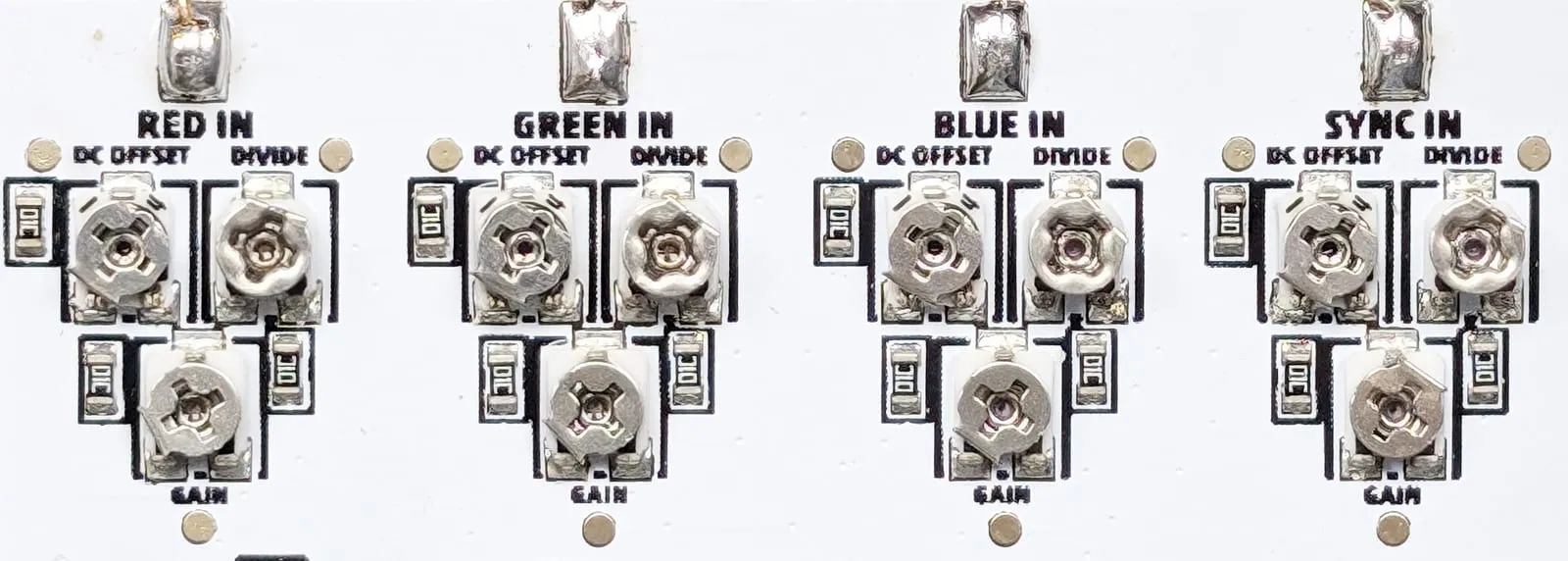
SNES (SNSP-CPU-02)
Section titled “SNES (SNSP-CPU-02)”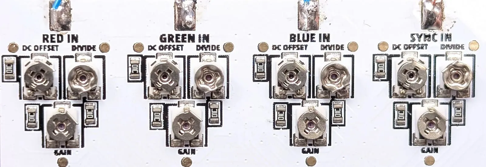
SNES (SNS-CPU-GPM-02)
Section titled “SNES (SNS-CPU-GPM-02)”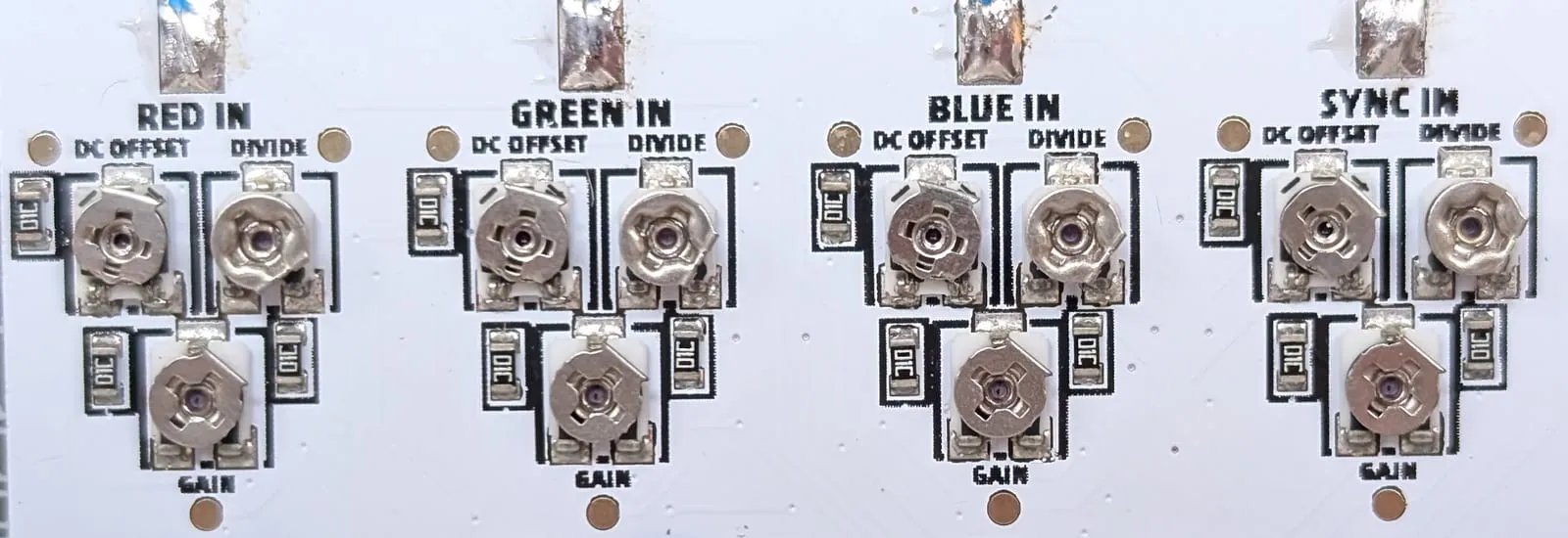
Amiga CD32
Section titled “Amiga CD32”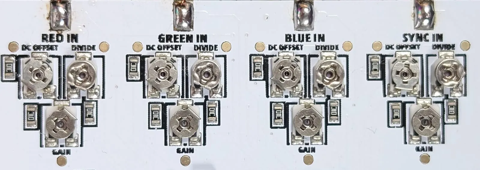
Tuning with a multimeter
Section titled “Tuning with a multimeter”Without an oscilloscope, the simplest way is to use the resistance table below. These are known resistance values for specific consoles that get you close enough to a perfect picture; tune the rest by eye.
| Potentiometer | Clockwise | Counterclockwise |
|---|---|---|
| DC Offset | More resistance = removes DC | Less resistance = signal unchanged |
| Divide | Less resistance = increase | More resistance = decrease |
| Gain | More resistance = increase | Less resistance = decrease |
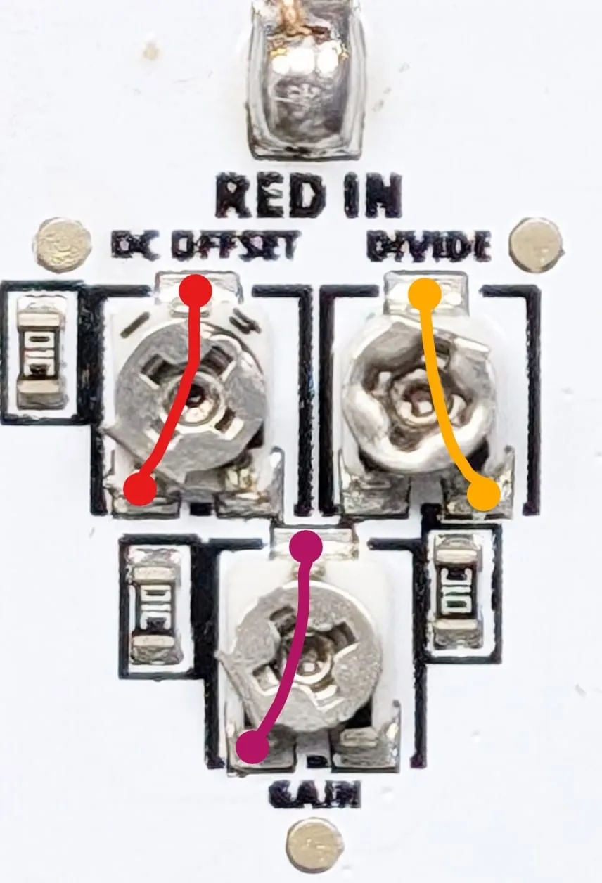
Measure the resistance between the two points of each pot as shown and turn the pot until you get the value.
| Console | DC | Divide | Gain |
|---|---|---|---|
| Master System | RGB 6.1k SYNC 6.1k | RGB 16.8k SYNC 16.8k | RGB 14.4k SYNC 0R |
| SNES / SFC (SNSP-CPU-02) | RGB 0R SYNC 5.45k | RGB 9.67k SYNC 14k | RGB 0R SYNC 0R |
| SNES / SFC (SNS-CPU-GPM-02) | RGB 0R SYNC 5.45k | RGB 11.9k SYNC 11.9k | RGB 0R SYNC 0R |
| Amiga CD32 | RGB 5.7k SYNC 5.7k | RGB 10k SYNC 10k | RGB 0R SYNC 0R |
Tuning with an oscilloscope
Section titled “Tuning with an oscilloscope”Because the CleanRGB is designed to be universal, it is configured with the pots on the board: first remove the DC offset, then divide or gain the signal to the correct voltage level.
This can be done by eye, with a multimeter or, most accurately, with an oscilloscope.
Repeat each of the following steps for the R, G, B and Sync inputs.
Target values
Section titled “Target values”The end goal is for the RGB output test pins to read 1.4V (lowest to highest voltage) when pure white is shown, and Sync to read 0.6V (it is often higher, which is generally fine for the sync pin).
As the circuit offsets the DC base to 0.2V, you will see a 0.2V offset followed by a 1.4V signal, giving a peak of 1.6V.
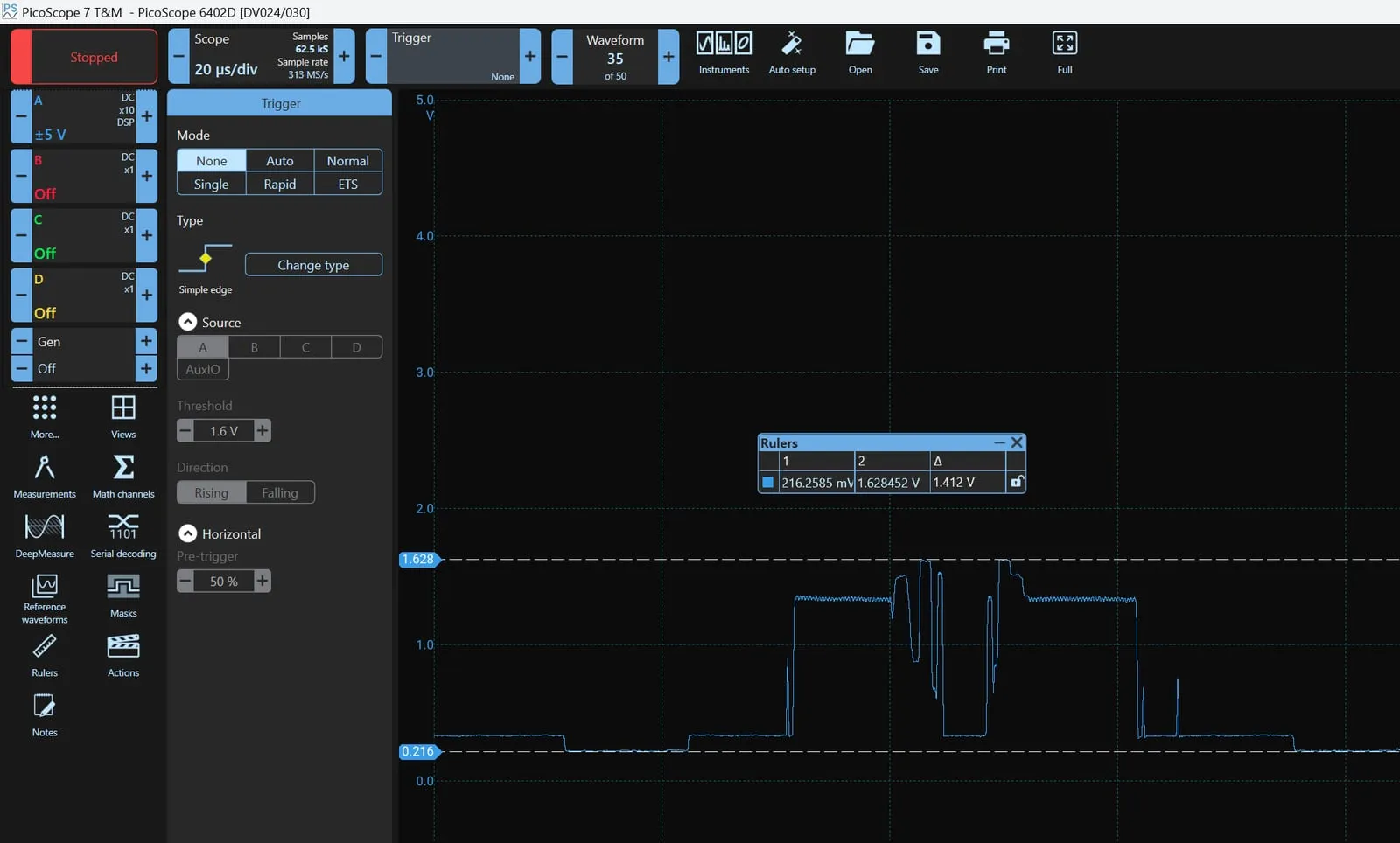
Although Sync should be 0.6V on paper, it is very common for sync to be a much higher voltage. A common value is 1.4V, just like the RGB values.
The highest some receivers accept on the Sync pin is 1V terminated / 2V floating, so ideally don’t exceed that.
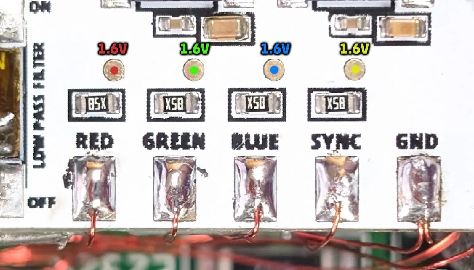
Measuring the input signal
Section titled “Measuring the input signal”Before setting the voltages, you must remove the DC offset from the input signal, then set the final voltage gain.
Turn on the console.
Measure the input signal to see where you are. These are, for example, the RED IN or BLUE IN pads where the wires were soldered to the CleanRGB. Here is the red signal coming in:
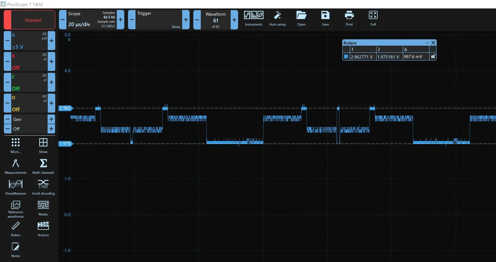
There are a few issues here. The voltage should be as close to 0V as possible without clipping the lower parts of the signal.
Secondly, the voltage level needs to be set to 1.6V at the final output stage (0.2V offset and 1.4V signal range).
Removing the DC offset
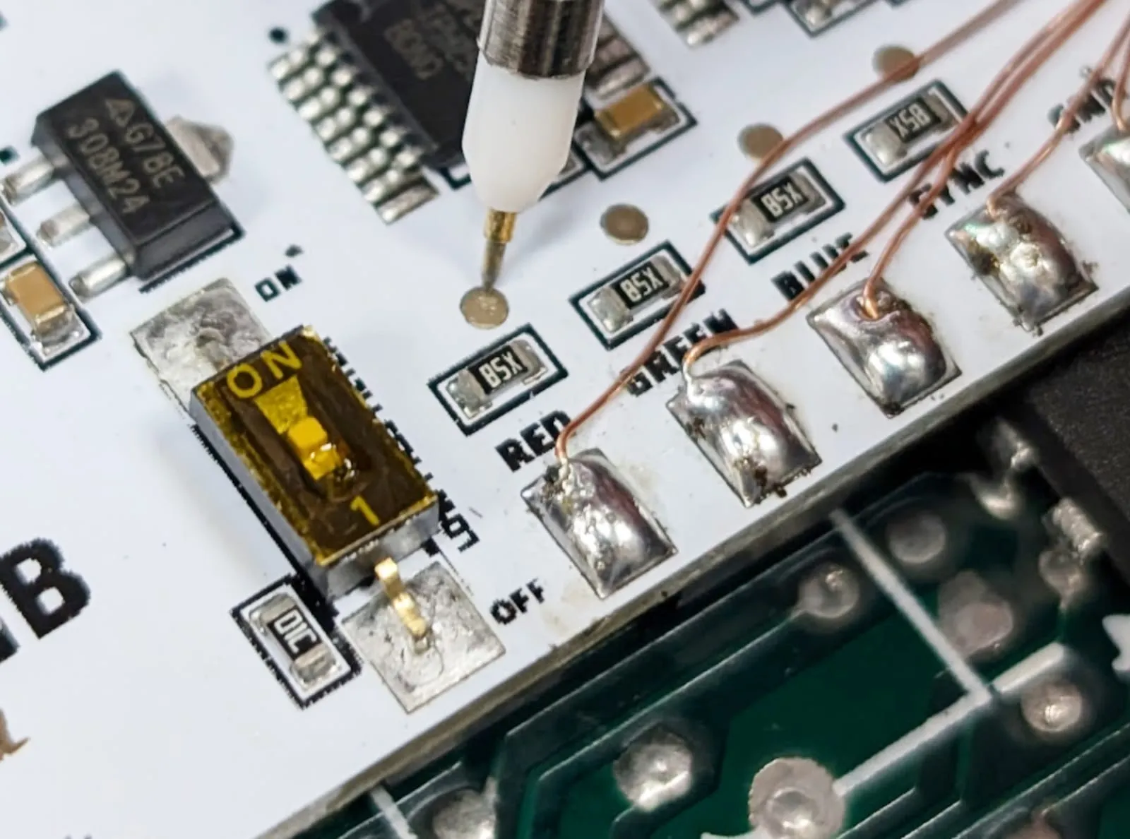
Section titled “Removing the DC offset”Start by removing the 2V DC offset. Probe the DC Offset test point and turn the DC offset pot.
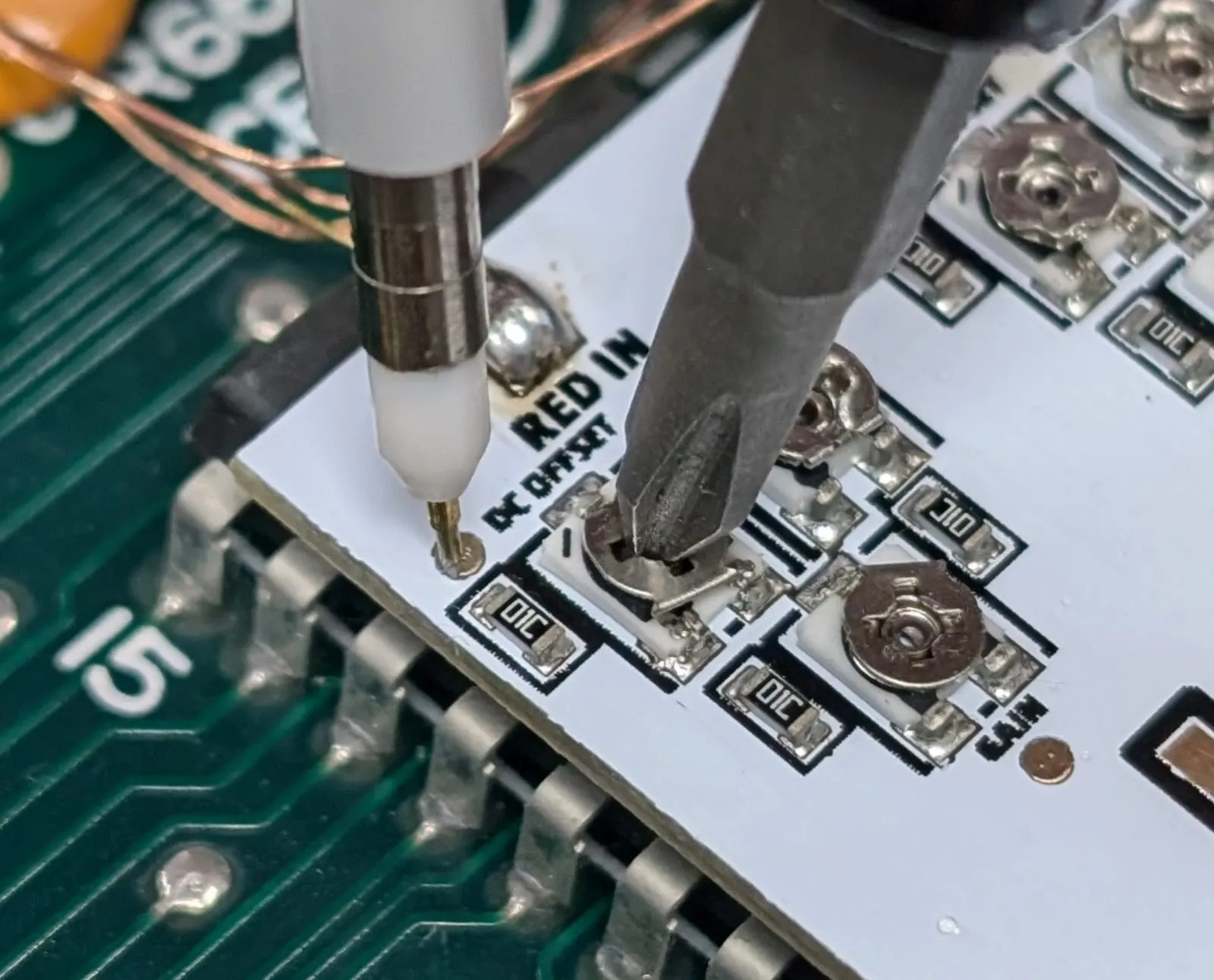
Turning the pot clockwise removes the DC offset (lowering the signal). Turn it until it is very close to 0V.
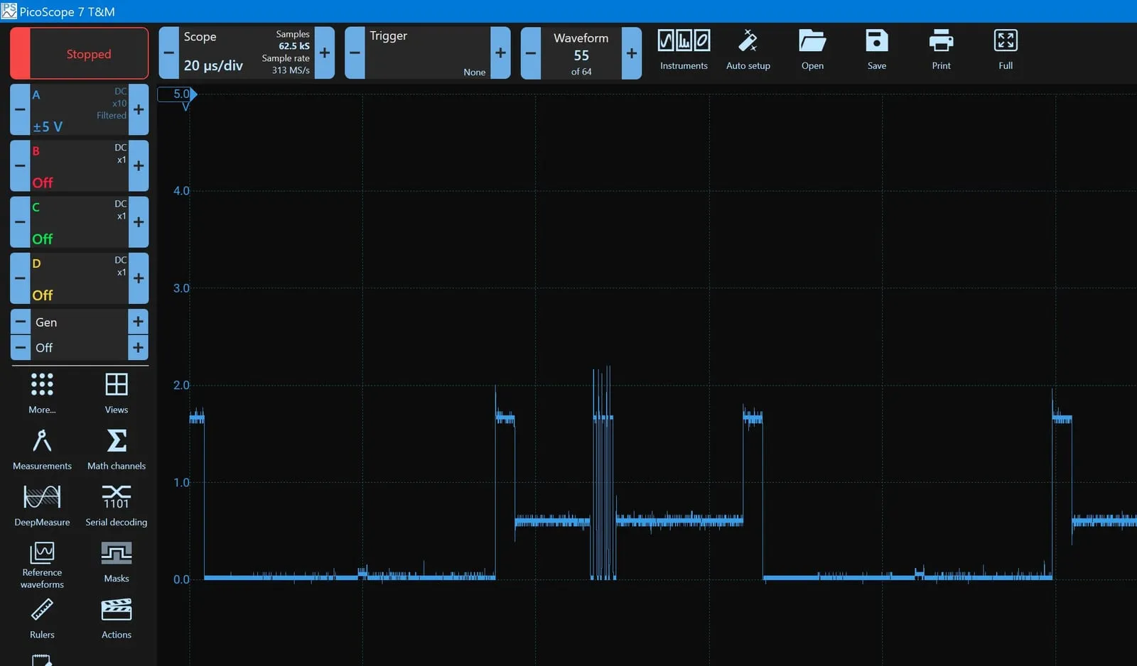
Setting the gain
Section titled “Setting the gain”The final step is to set the output voltage. Probe the final stage test pad. This pad ignores the receiver’s pull-down, so whether or not a receiver is connected, the output should be 1.6V when 100% brightness is shown on screen (0.2V offset and 1.4V signal range).
Technically the Sync signal should be 0.6V, but almost all receivers are happy with a Sync signal anywhere from 0.3V to 5V, so this is much less critical.
The goal is to tune the Divide and Gain pots until the peaks are at 1.6V.
Turning either pot counterclockwise reduces the signal, turning it clockwise increases it.
The closer the Divide pot is turned to 0 ohm, the less the signal is affected, meaning it won’t be divided. The higher the resistance (up to the maximum of 47k), the more the signal is reduced.
Turn either or both pots until you reach 1.6V.
Ignore the capacitive spikes on the signal: the 1.6V refers to the flat parts of the actual signal.
Once you’re happy, do the final tuning by eye. If the colour tone is off, for example too much red tint, reduce red by turning Divide or Gain counterclockwise.
The final output should be RGB at 1.6V and Sync at 0.6V to 5V, depending on the output or screen position you want.
Install: Master System
Section titled “Install: Master System”The Master System already outputs RGB from the AV port, but with a DC offset that puts the voltage levels off for most monitors.
Most people solve this with custom RGB cables with AC coupling capacitors and resistors. That works, but it’s far from perfect: it brings all the problems AC capacitors add (field droop, tilt, common-mode noise coupling from the receiver side and more).
The CleanRGB instead fixes the console itself so it outputs IRE-correct voltage levels and signals. The cable is then a pure DC cable with direct connections, no hidden capacitors, sync strippers, resistors or other magic. The result is clean RGB signals that aren’t affected by your cable, receiver or noise.
This install involves:
- Getting the RGB and Sync inputs from the CXA1145 to the CleanRGB
- Severing the traces from the CXA1145 RGB and Sync outputs to the AV port
- Wiring the CleanRGB RGB and Sync outputs back to the AV port
- Tuning the CleanRGB for correct IRE levels
Wiring the RGB inputs
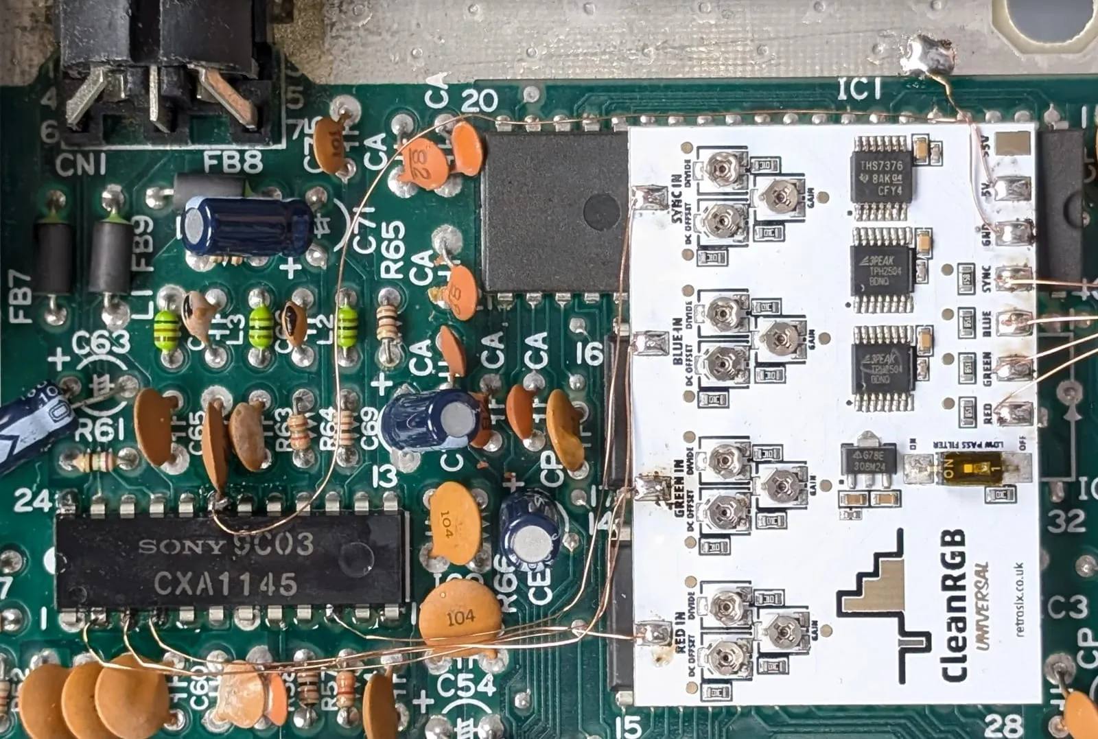
Section titled “Wiring the RGB inputs”Install the CleanRGB Universal board in the Master System. Tap the RGB and Sync inputs directly from the CXA1145.
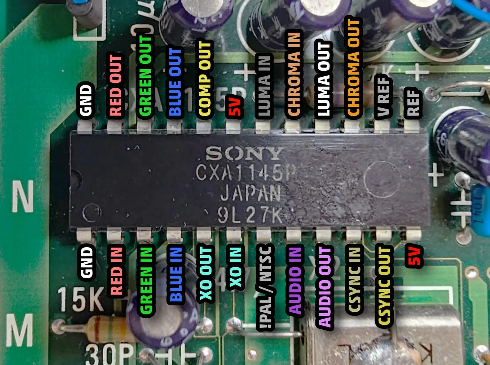
R, G and B In go to the CleanRGB inputs. Take 5V from CXA pin 19 and ground from the nearby ground.
Disconnecting the AV port from the CXA
Section titled “Disconnecting the AV port from the CXA”Next, disconnect the AV port from its existing connection to the CXA1145.
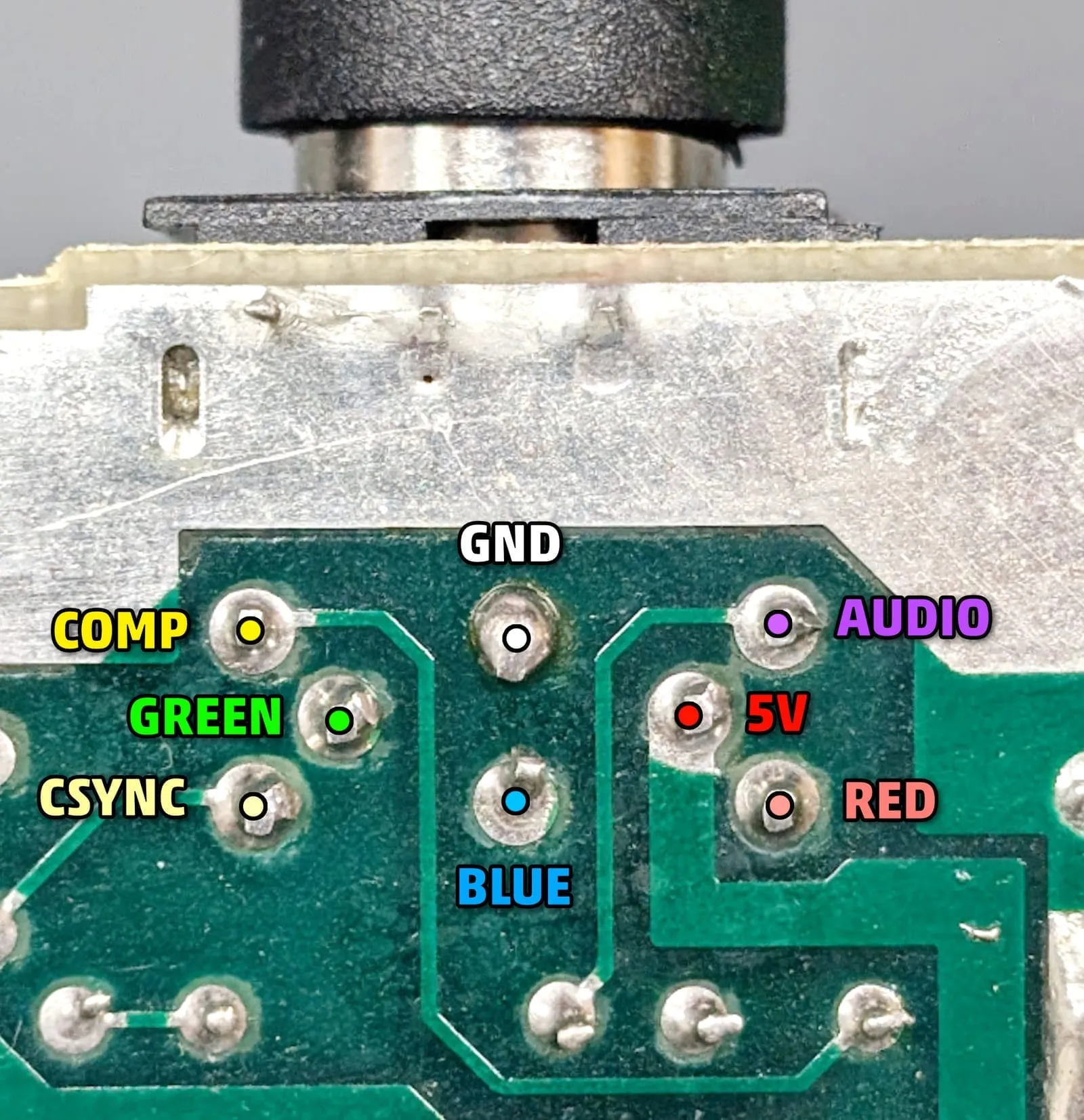
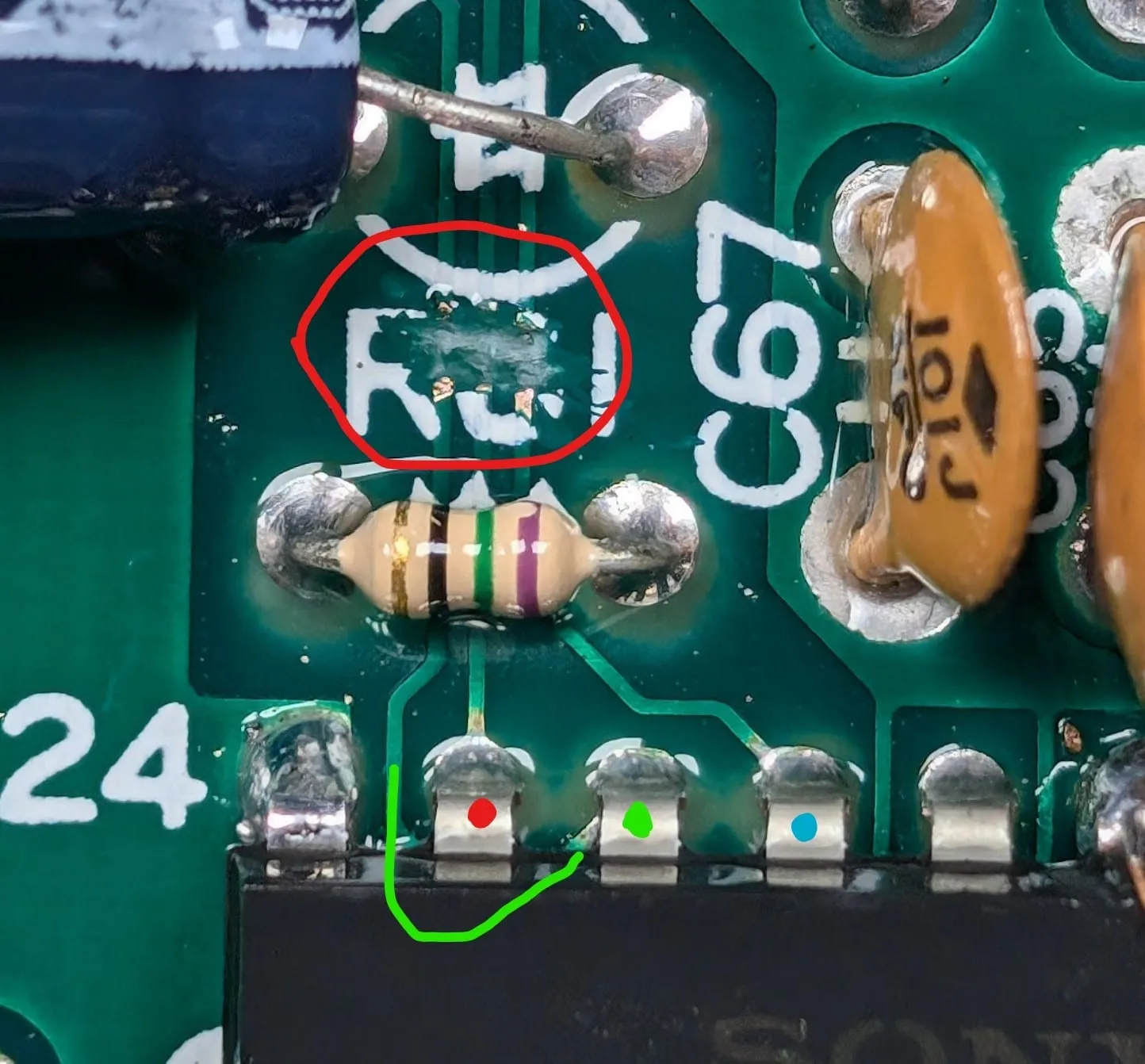
The R, G and B traces usually run together right next to the output pins. Check with a continuity test or follow them visually. On this revision they are here and easy to sever.
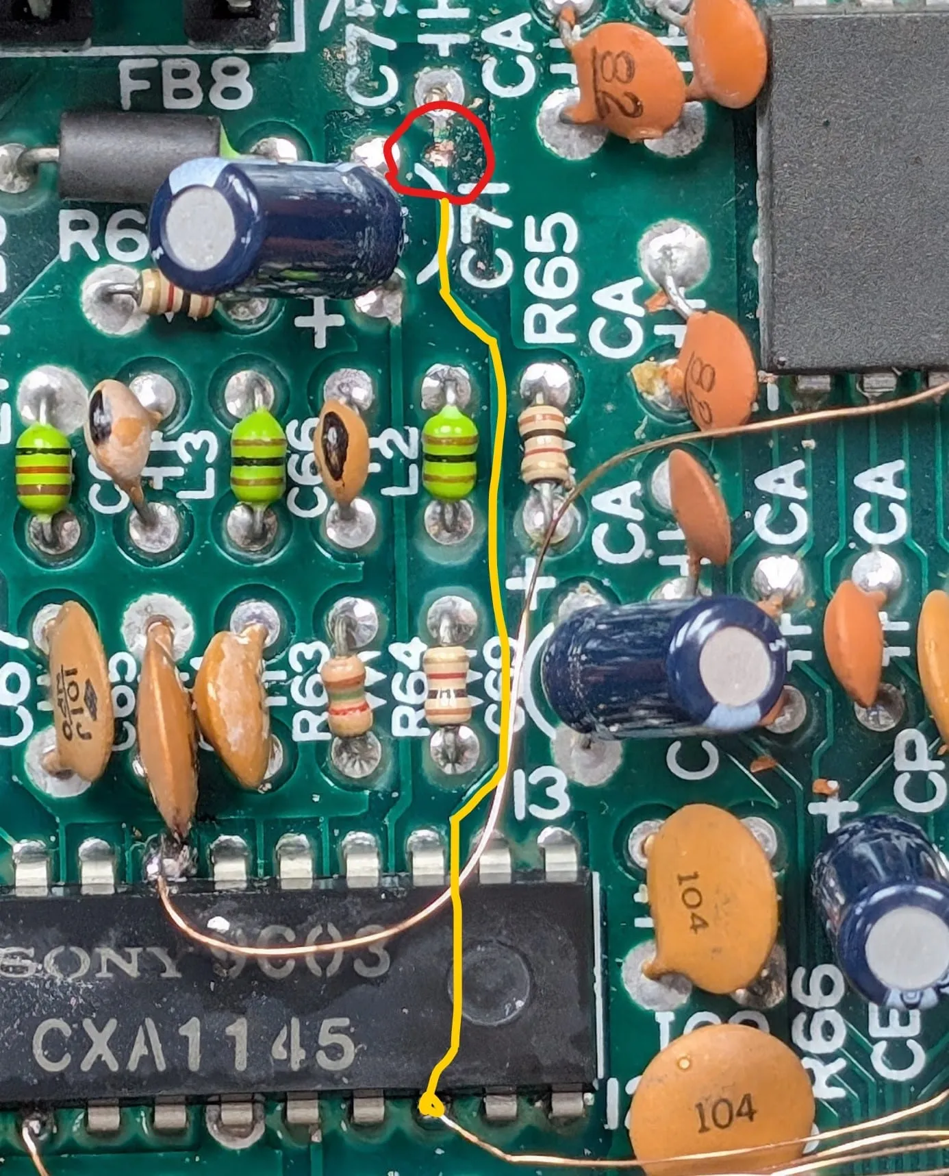
Finally, do the same for the connection from CSYNC pin 10 of the CXA1145 (CSYNC In, not Out) to the CSYNC pin of the AV port.
Connecting the CleanRGB output
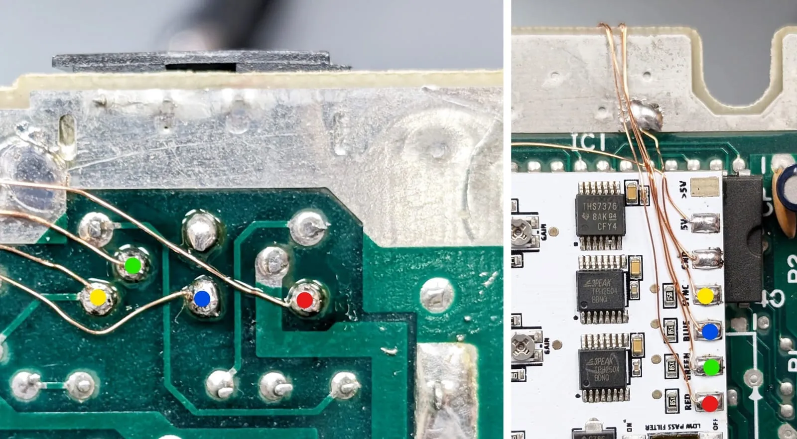
Section titled “Connecting the CleanRGB output”Now wire the RGB and Sync outputs to the AV port pins.
Tuning
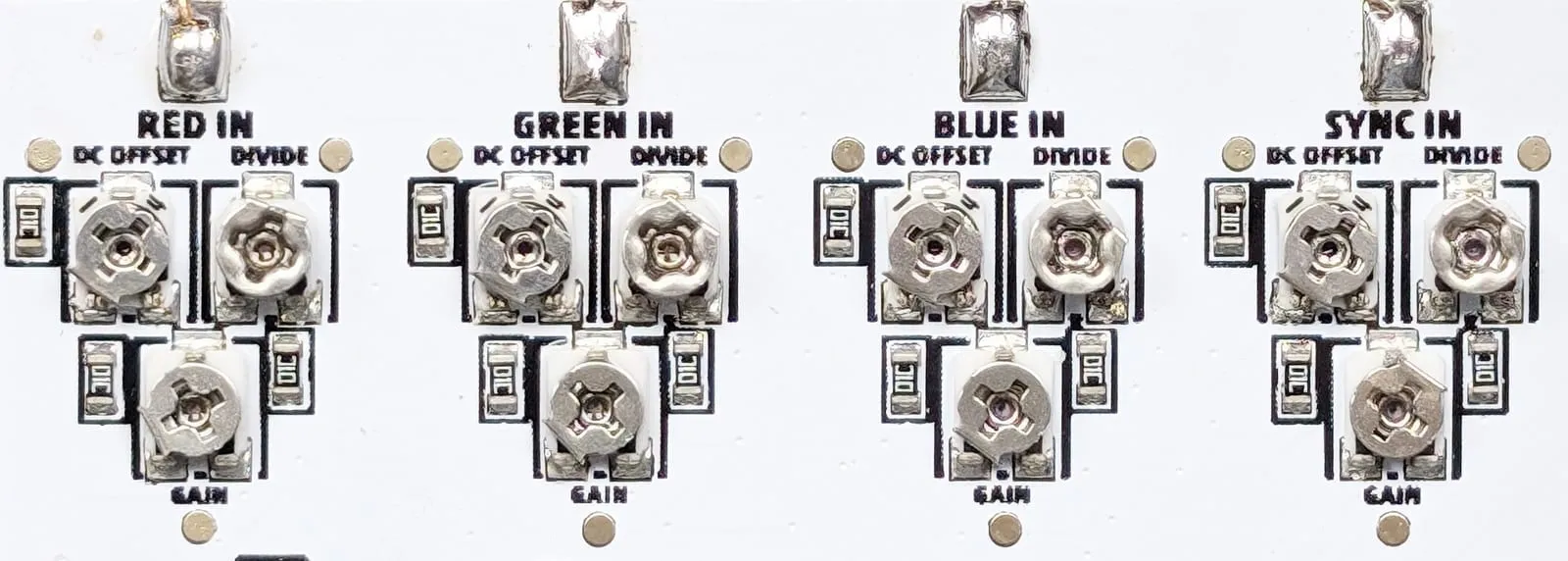
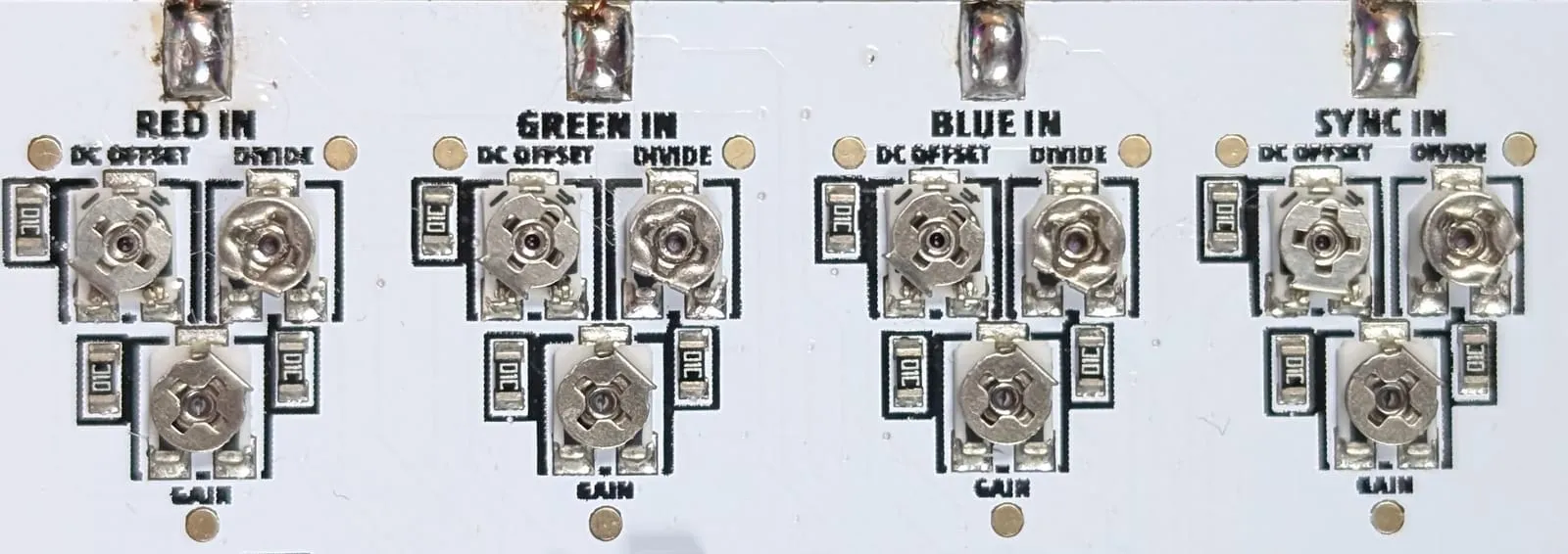
Section titled “Tuning”Tune the CleanRGB as described above. For a quick start, set the dials to these positions and then fine-tune by eye.
Results
Section titled “Results”Here are the results on a Master System with the CleanRGB SCART cable.
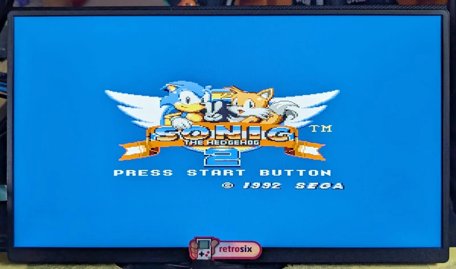
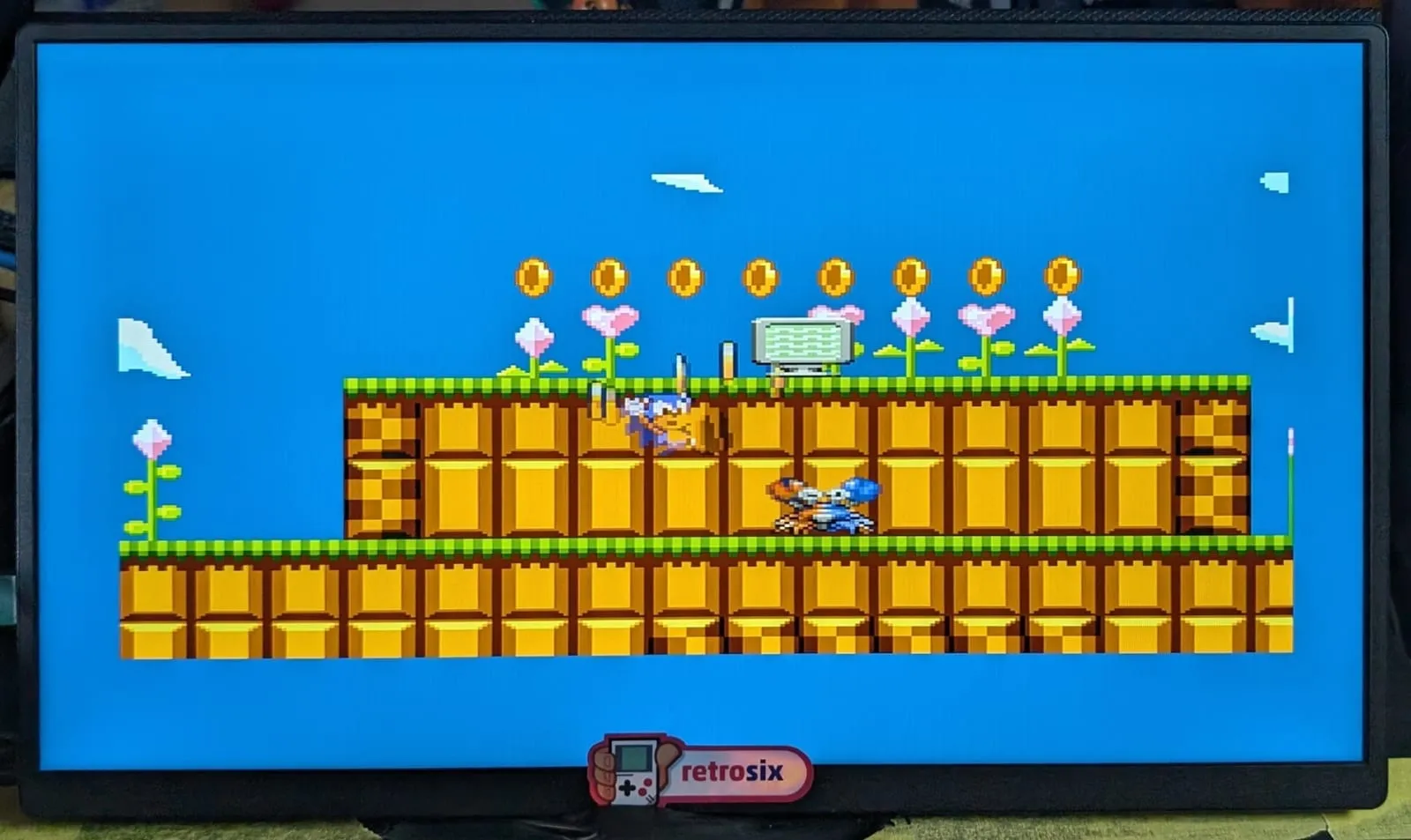
Install: Neo Geo AES
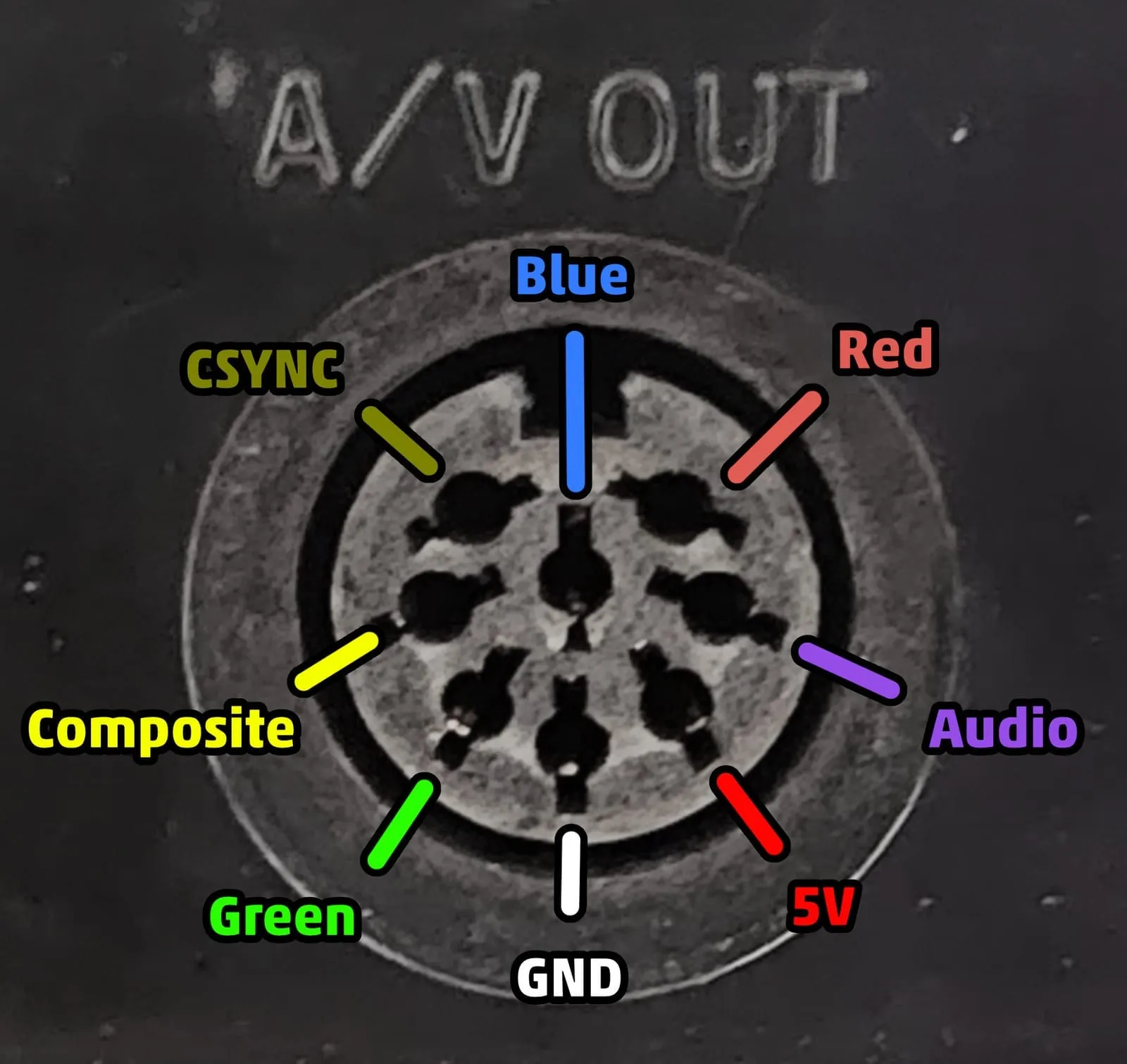
Section titled “Install: Neo Geo AES”The Neo Geo AES consoles already route RGB to their output port, ready for CleanRGB cables. You can simply connect the CleanRGB cable to any Neo Geo AES model.
Recommendations
Section titled “Recommendations”The Neo Geo AES models vary a lot and all have different internal RGB circuit designs. It’s best to open the console and check whether some mods would improve the picture:
- CSYNC Mod (fixes checkerboards)
- RGB Voltage Levels (fixes brightness)
- Clock Trace Removal (fixes jailbars)
- Ghosting Fix (fixes ghosting)
Install: Amiga CD32
Section titled “Install: Amiga CD32”The Amiga CD32 doesn’t output RGB natively, only composite, S-Video and RF. The internal ICs do have RGB that can be tapped.
Most people add RGB with custom cables using AC coupling capacitors and resistors. That works, but it brings all the problems AC capacitors add (field droop, tilt, common-mode noise coupling from the receiver side and more). The CleanRGB instead fixes the console itself, and the cable is a pure DC cable with direct connections.
This install involves:
- Getting the RGB and Sync inputs from the CXA1145 to the CleanRGB
- Removing the S-Video port and epoxying in a Master System RGB port
- Wiring the CleanRGB RGB and Sync outputs to the AV port
- Tuning the CleanRGB for correct IRE levels
- Opening up the AV port hole with a drill
Fitting the AV port
Section titled “Fitting the AV port”Start by removing the old S-Video connector (hot air works well).
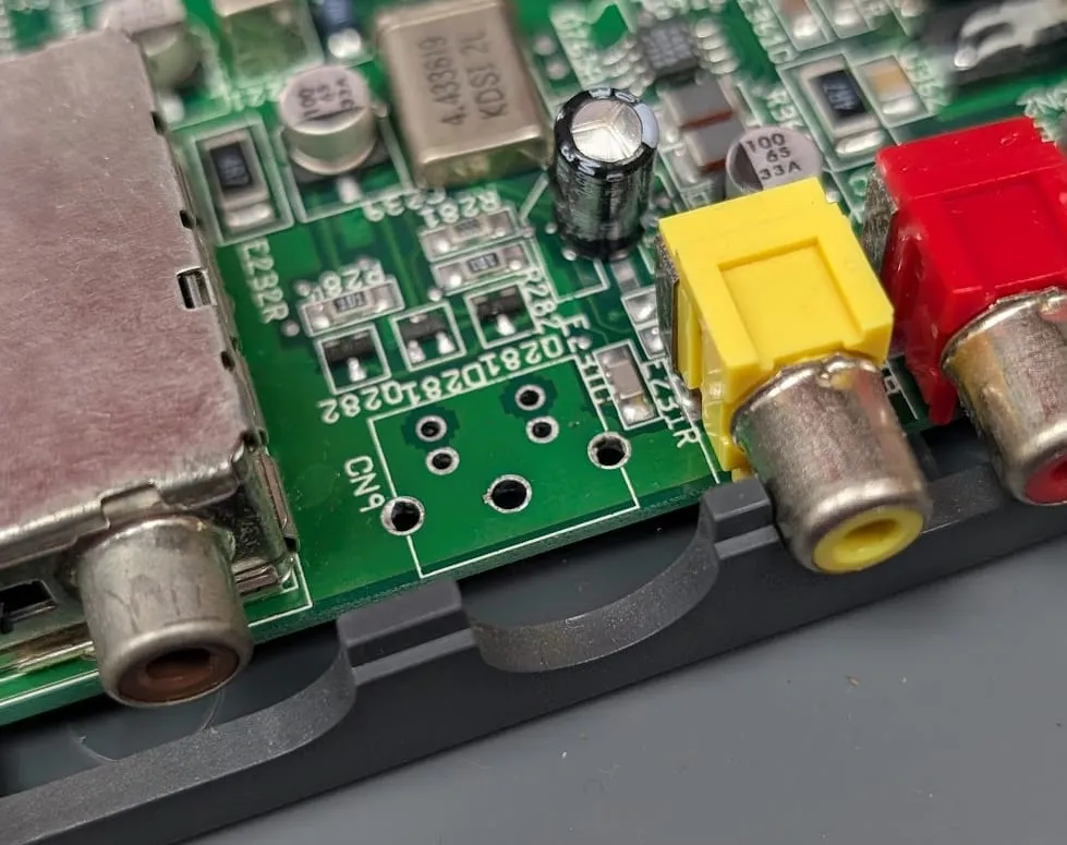
Secure the Master System RGB AV port upside down in its place with epoxy or similar.
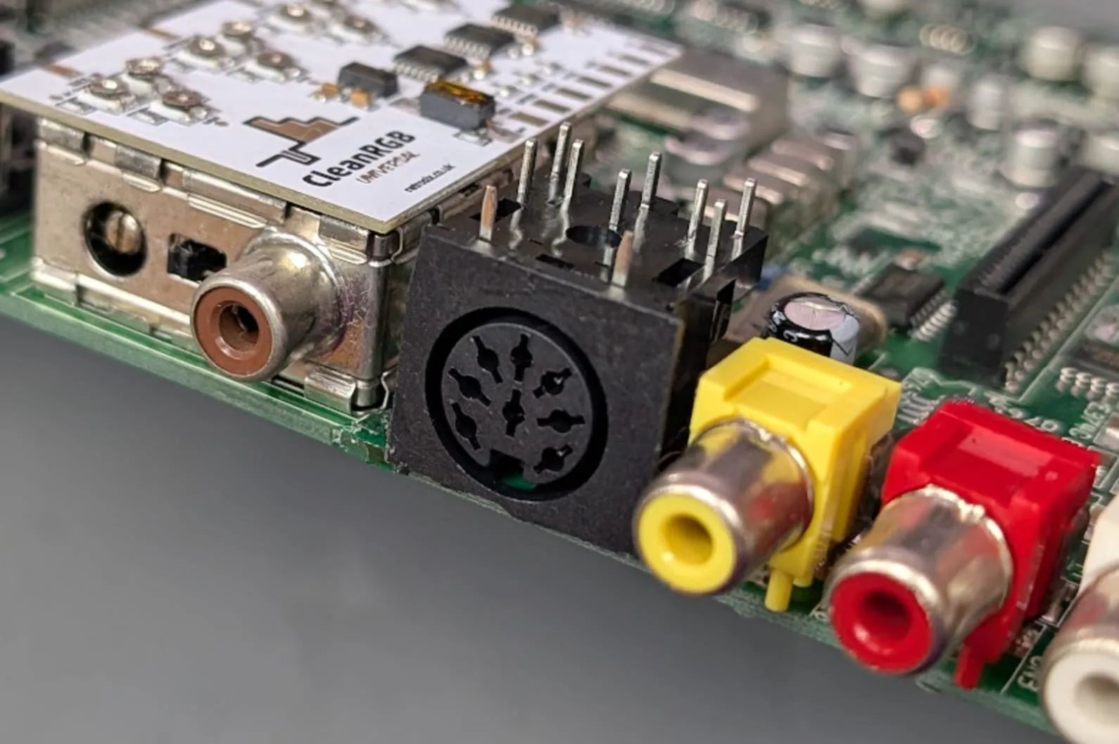
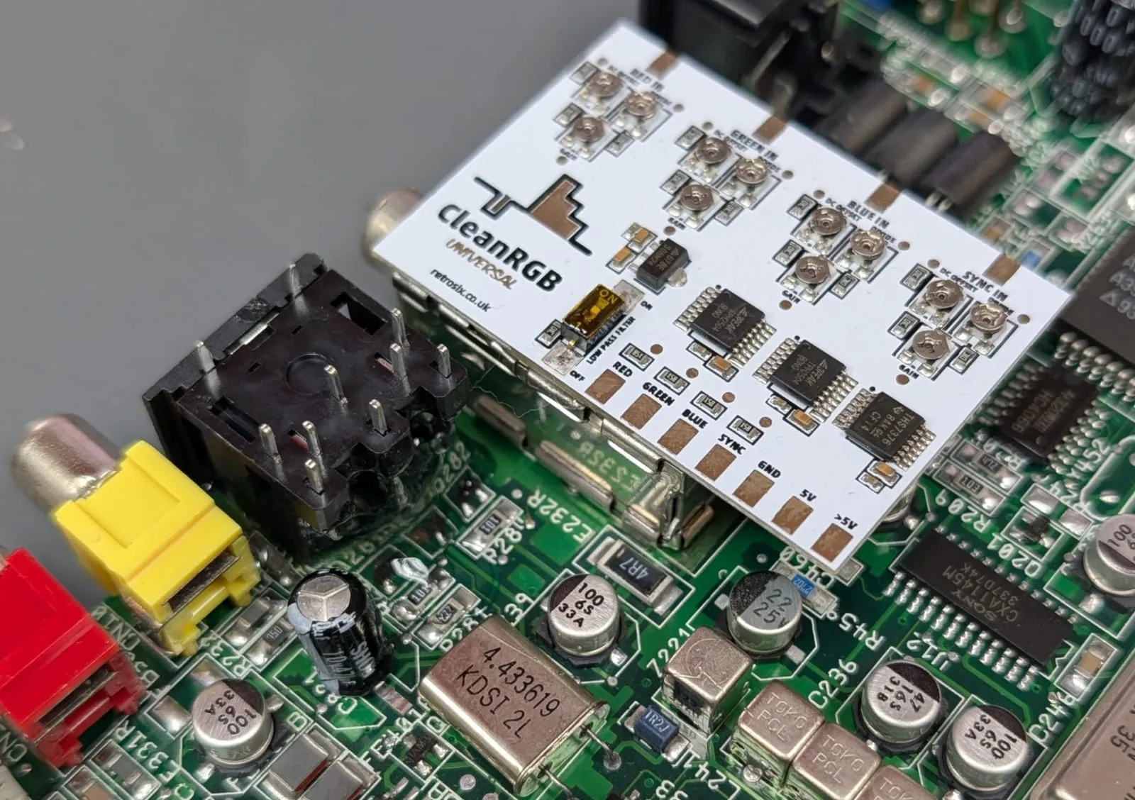
Next, stick the CleanRGB board on top of the RF connector.
Wiring the RGB inputs
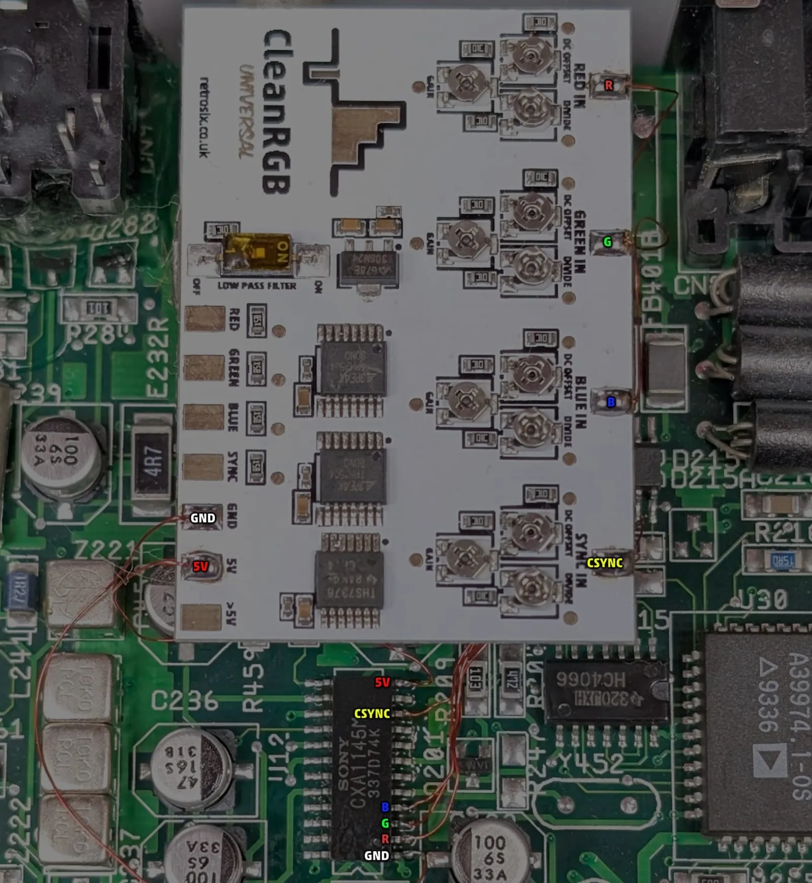
Section titled “Wiring the RGB inputs”Wire GND, 5V, RGB In and Sync In on the CleanRGB to the CXA1145.
Connecting the CleanRGB output
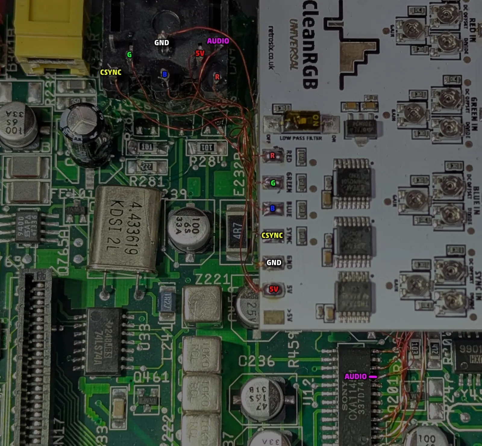
Section titled “Connecting the CleanRGB output”Now wire the RGB and Sync outputs, along with GND, 5V and audio, to the AV port pins.
Tuning
Section titled “Tuning”Tune the CleanRGB as described above. For a quick start, set the dials to these positions and then fine-tune by eye.
Widening the hole
Section titled “Widening the hole”The shell needs slightly widening so the Master System cable fits through, for example with a suitable drill bit.
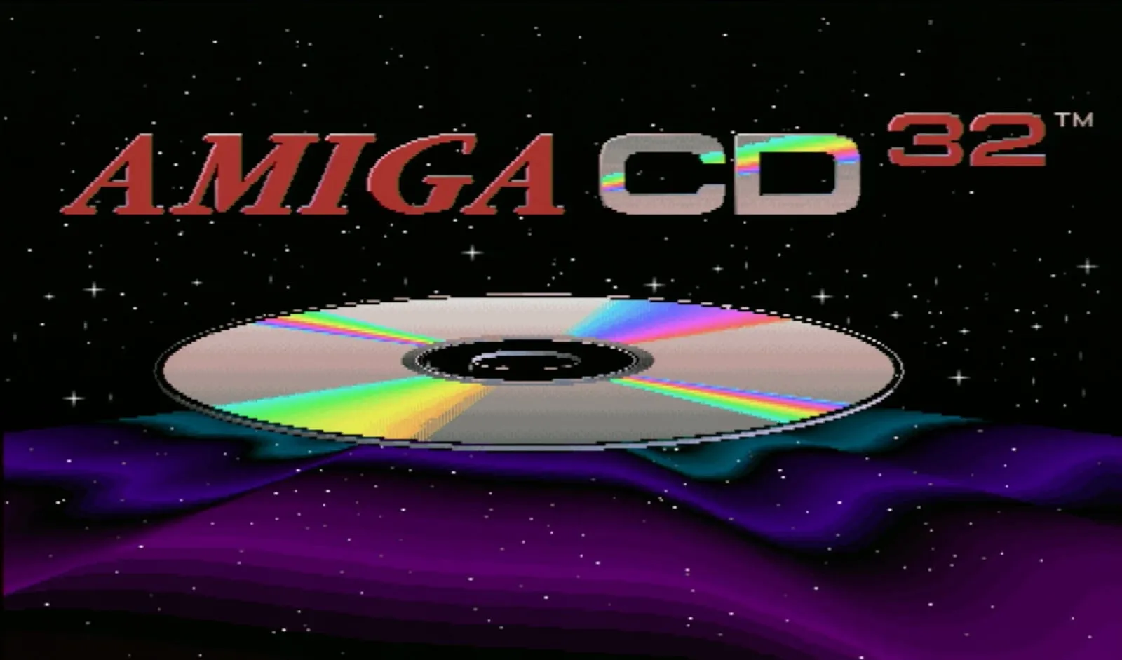
Results
Section titled “Results”Here are the results on an Amiga CD32 with the CleanRGB SCART cable.
Install: Mega Drive 2
Section titled “Install: Mega Drive 2”The CleanRGB for the Mega Drive 2 gives you RGB output with correct IRE levels. The install guide is a video: