
[GBASP] RetroSix Wire Free Dehum Dehiss
The Game Boy Advance SP is known to have the most audio noise of all the Game Boy consoles. Many people believed the amp in the GBA SP itself was noisy. But when the original amp is lifted, hooked up on a separate PCB and driven with a clean function generator signal, it amplifies the audio perfectly clean with no noise, just like the GBA amp. The noise is made by the console itself.
As you add amplifiers like the CleanAmp (see [GBASP] RS CleanAmp Universal), the noise gets much worse, enough to really annoy people and distract from playing.
The usual solutions try to filter out the noise with simple low pass filters, which effectively removes most of the original sound as well. The goal here is to fix the cause, not mask it.
The Wire Free Dehum Dehiss Kit puts the right capacitors on a small board. They filter the noise produced by the CPU, SRAM and power regulator. It’s easy to install, basic soldering skills are enough. “Wire Free” means no individual wires, you still need to solder it in.
Installing the Wire Free Dehum Dehiss Kit
Section titled “Installing the Wire Free Dehum Dehiss Kit”-
Get your tools ready: a screwdriver to open the console, a soldering iron, solder, flux, tweezers and IPA (isopropyl alcohol) for cleaning. If a capacitor is missing on your board (see step 4), you’ll also need a short piece of thin wire, ideally 28 AWG, no thicker than 26 AWG.
-
Open the console, see [GBASP] Shell Disassembly. If you want to clean the volume slider and the power switch (Cleaning the slider and switch), do it now: the kit gets soldered onto the metal housing of the switch later.
-
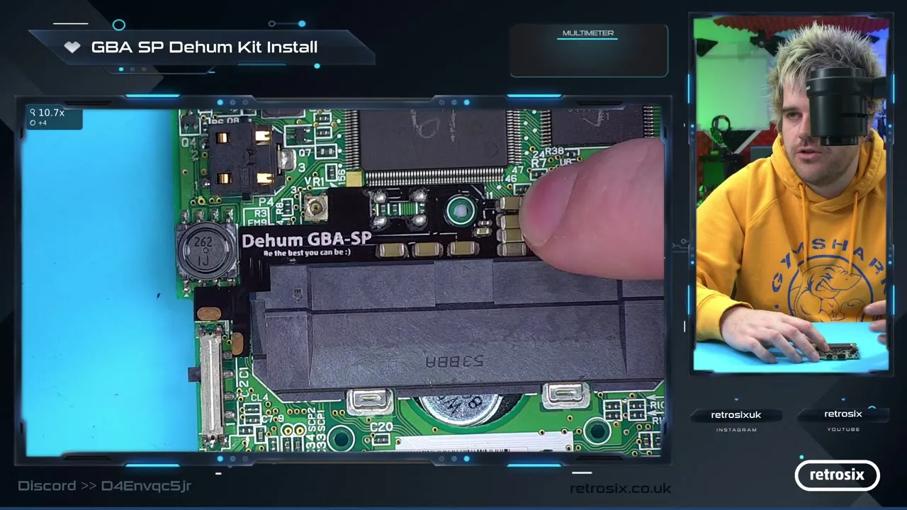
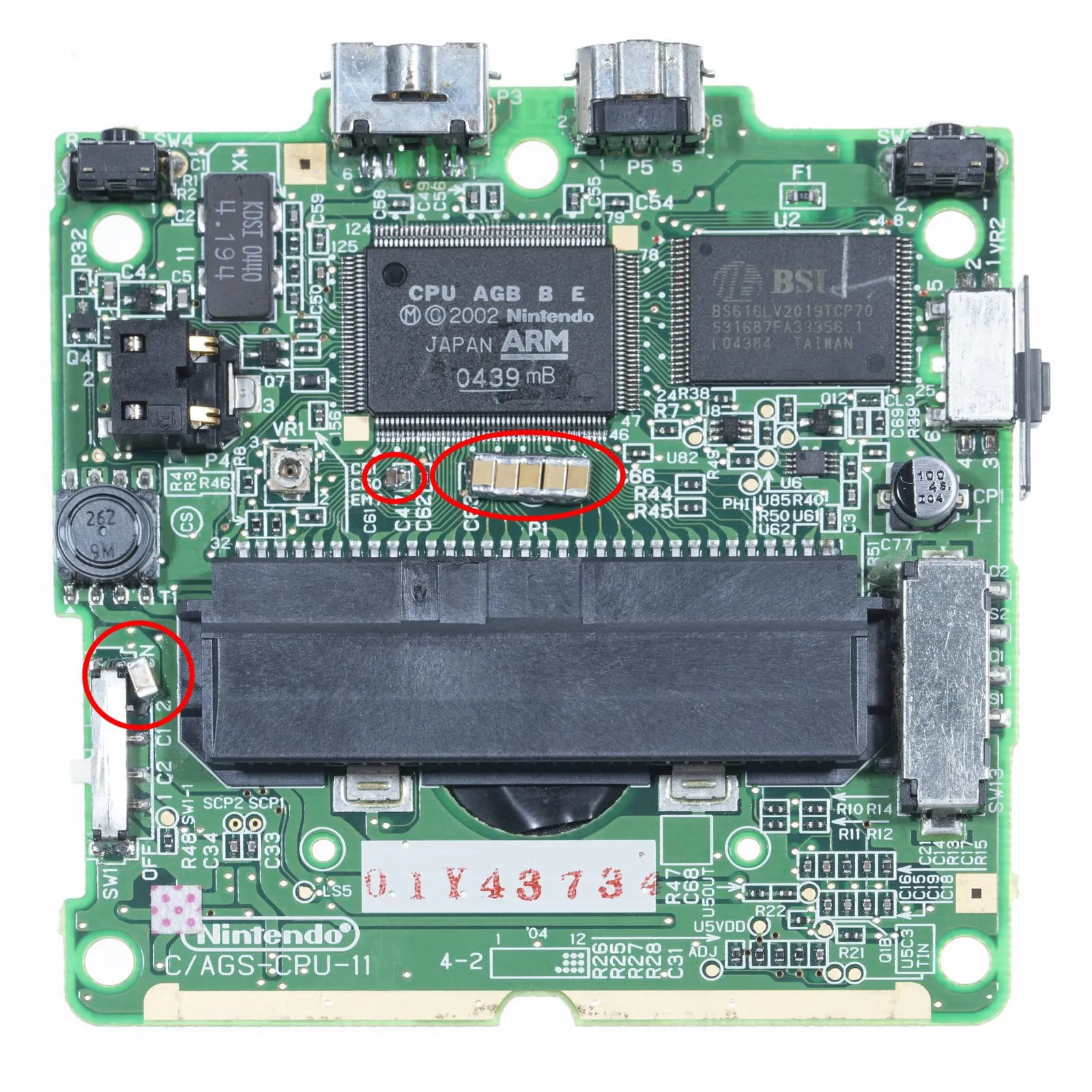
Place the kit on the board. It’s fairly obvious where it goes: it sits over the screw hole, reaches down to the power switch and fits snugly in the console.
-
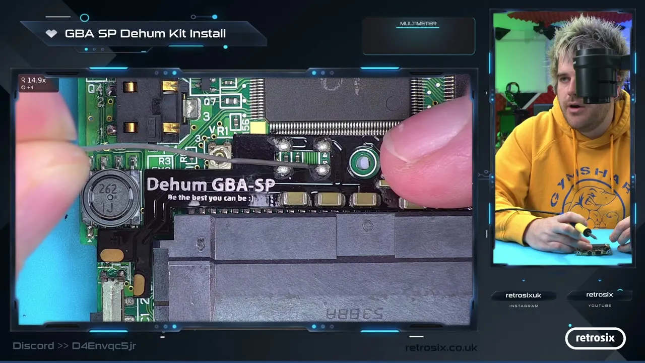
Align the kit accurately. You’ll solder to the top and bottom pads of two capacitors, one of them being C63, and to the power pins at the power switch. Position the kit based on the capacitor pads first, because those joints are the hardest. If C63 is missing on your board (as in the video), it’s not a big deal, because the kit itself adds extra capacitors.
-
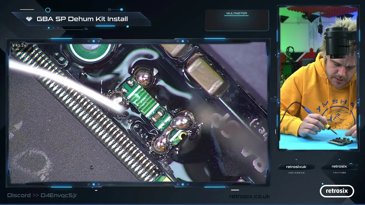
Apply flux to the pads to keep the solder flowing nicely. Tack the kit in place with a solder blob on the existing capacitor first, then solder the other side of that capacitor.
-
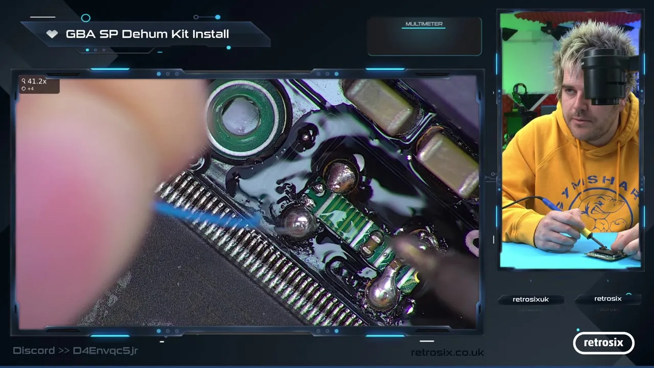
Solder the kit to the top and bottom of C63. If there is a capacitor in place, this is just as easy as the previous step. If the capacitor is missing, bridge the gap with a short piece of wire: place the wire on the small pad, add solder and trim the excess wire. Don’t worry too much about knocking off an original capacitor while you work: the kit adds that capacitance back to the system anyway, and more.
-
Clean the area with IPA and check that all joints sit properly on the pads and capacitors. That’s the tricky part done.
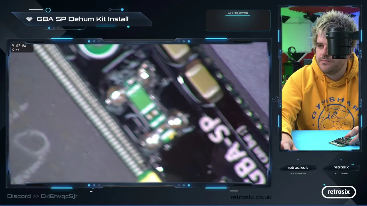
-
Pre-tin the pad on the power switch and the matching pad on the kit. Hold the kit down with tweezers and solder it with plenty of solder. It’s a nice big pad, so this is easy.
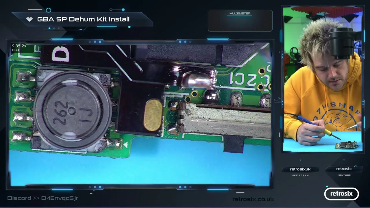
-
The second pad is ground. Pre-tin the metal contacts of the switch housing, place the kit on them and solder it. Flatten it down a little if needed. That makes six solder blobs in total. The screw hole stays accessible with the kit, but a CleanAmp installed over it covers it.
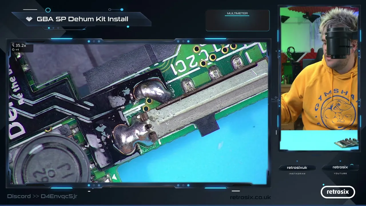
-
Before powering up, check that the top and bottom capacitor pads aren’t bridged.
- Power up the console and compare the sound with before. The noise is significantly reduced. On the SP it’s not completely gone, a little noise remains, but compared to the original the difference is huge. Especially with an amp like the CleanAmp, the sound is barely usable without the kit.
Cleaning the slider and switch
Section titled “Cleaning the slider and switch”The volume slider and the power switch can add noise as well. Cleaning both is worth it whether you install the kit or individual capacitors.
The volume slider
Section titled “The volume slider”The volume slider is referenced to ground and also fed into the amplifier on the GBA SP to adjust the output stage. Any dirt that builds up in the slider can add feedback to the ground plane, causing noise. The amount of noise this adds is usually small, but it’s still worth fixing.
Put some IPA (isopropyl alcohol) on the slider, then slide the volume wheel up and down about 20 times. This presses the metal contacts inside the slider firmly against the metal PCB contacts and rubs them. Together with the IPA, this scrubs the contacts clean.
The power switch
Section titled “The power switch”The power switch on the GBA SP is known to build up a black grime over time. It looks like copper oxidation.
Using a soldering iron, add some solder to one side of the metal housing that holds the plastic power switch in place. Get tweezers inside the metal housing, between the metal and the power switch, and as you heat one side of the metal solder pad with the iron, gently lift the metal up. Be careful not to flick the metal up: it’s springy and can flick molten solder towards you. Wearing eye protection is a good idea.
Now remove the plastic power switch and you will see the dirt inside the switch.
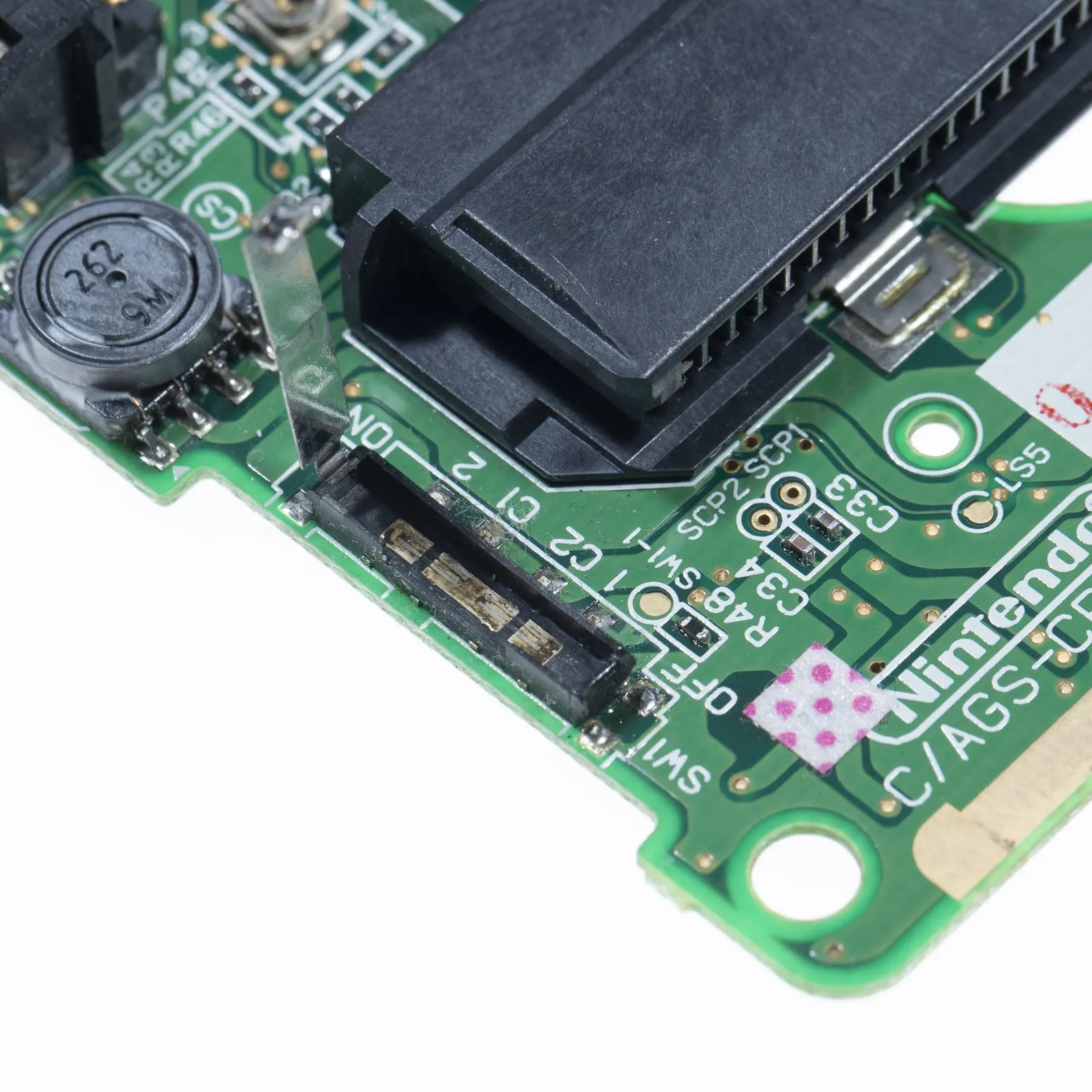
The contacts should be clean copper/gold, but they are usually blackened. Drop some IPA into the switch and gently rub sideways with the tweezers until the dirt comes loose. Use a cotton bud dipped in more IPA to wipe the loose dirt away. Repeat once or twice.
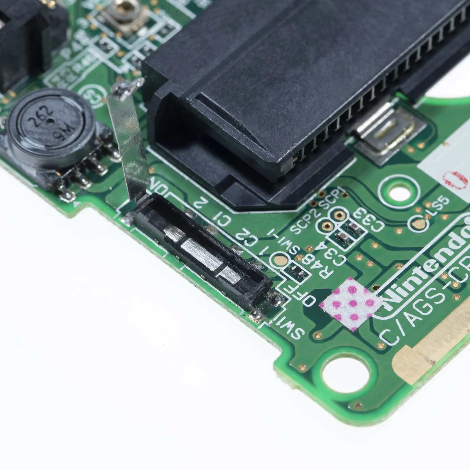
Put the power switch back in place and re-solder the metal cover.
Alternative: individual capacitors (without the kit)
Section titled “Alternative: individual capacitors (without the kit)”Many components in the SP are the same as in the GBA, some are not. Here are the fixes for all of them.
The loud hiss
Section titled “The loud hiss”This is one of the two very loud noises on the system, and its source had never been found. The cause: the VDD3 power rail is very noisy, because it is shared with the SRAM and the CPU as well as other high speed lines.
The main cause of the noise is insufficient bypass capacitors near the CPU and SRAM to supply the quick bursts of power they need. When a chip is switching fast, it needs fast current locally, that’s the purpose of bypass capacitors. A lack of capacitance near the switching pins means the power rail dips and rises in and out of phase with the switching, causing the noise. On systems without audio output this isn’t always audible or noticeable, but on the GBA with its audio output it is very noticeable.
This noise introduced by the CPU and SRAM causes the hiss (the high pitched noise).
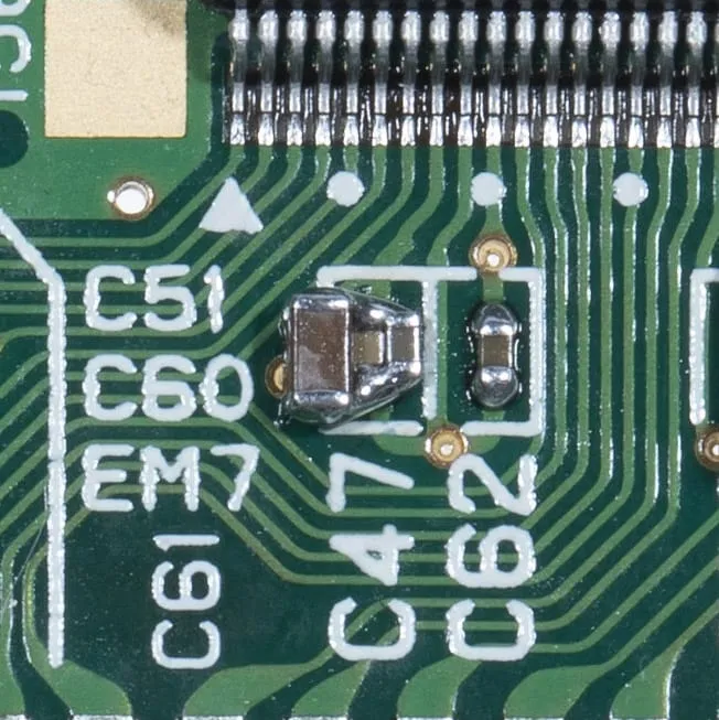
The best spot and the best value capacitor to remove this hiss completely is C47, to the bottom left of the CPU. Leave C47 in place and solder an additional 1uF and 10uF capacitor to it, rated at least 6.3V. If you cannot fit the new capacitor on the same pads as C47, solder one side of the new capacitor to one side of C47 and use a small jumper wire to connect the other side. If you position it just right and are handy at soldering, you won’t need any wire.
With this capacitor in place, almost all audible noise is gone.
You can also stack the capacitors on top of one another instead of side by side.
The capacitors you need are included in the Dehum Dehiss kit for the GBA SP. If the kit includes aluminium capacitors, you don’t need them on the SP, they are only needed for the GBA.
The low hum
Section titled “The low hum”Unlike the GBA, the GBA SP has a newer, higher speed, more efficient power regulation circuit that does not suffer from the GBA’s low hum when running original GB and GBC games. When running GBA games, however, it is unfortunately even worse than the GBA. The extra power draw and the different core voltage the CPU uses for GBA games introduce a terrible low flutter hum.
That’s why the primary VCC power rail at C63 needs extra bulk capacitance. As space in the SP is limited, the only way to do this is with five 220uF capacitors in a row. If you are using an amp other than the CleanAmp, you can spread the capacitors around the screw hole and wire them together. As the CleanAmp sits over this screw hole, with it you can cover the hole.
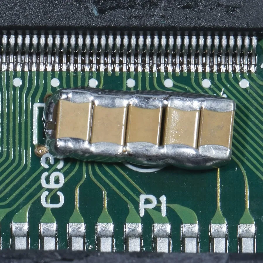
Solder one capacitor to C63, then daisy chain the other four. This removes the low flutter when playing GBA games.
Over current noise
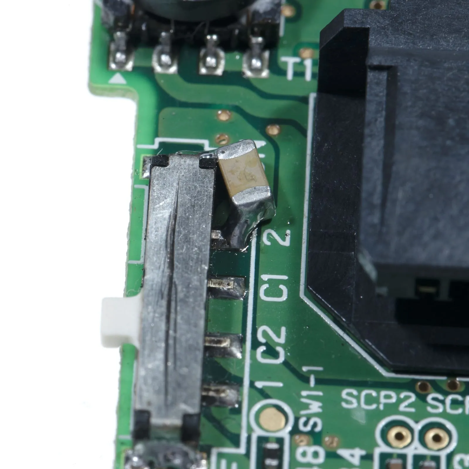
Section titled “Over current noise”The SP has a better designed power system, so it doesn’t struggle as much to keep the supply clean under the slow, heavy current draw of IPS mods or other power hungry mods, but it does need a little help. Add a 220uF capacitor (the same type as on C63) to the main power input on the switch, between the ground shield and pin 2 as shown. Be careful not to short pin 2 and the ground pads together.
The white noise
Section titled “The white noise”The last noise left after filtering the hiss and hum is the white noise caused by the system as a whole.
The CPU, power, audio, LCD and RAM all carry high speed signals, and without perfect ground returns, decoupling capacitors and a very clean board you will never remove every bit of white noise.
The good news: with the steps above, the white noise on the GBA SP is even lower than on the GBA and basically inaudible. You should now have crystal clear audio.
Does it improve the headphones?
Section titled “Does it improve the headphones?”Yes. Filtered correctly like this, the noise is not present on the headphones either.
Buying the parts
Section titled “Buying the parts”You’ll find the Dehum Dehiss kit for the GBA SP to remove hum and hiss in our shop; for amplifying the audio see [GBASP] RS CleanAmp Universal.
Feedback
Section titled “Feedback”If you’d like to give feedback on this article or help out, there is an open discussion on the RetroSix forum.