
[DMG] Q5 RIPS Laminated IPS Kit by Hispeedido
Foreword
Section titled “Foreword”- Always do a function test BEFORE you install the IPS kit! Kits that have already been installed cannot be returned under warranty. You can see how to test the kit externally here: How do I test the LCD
- The LCD is very fragile and sensitive to pressure, impacts, etc. Please be especially careful when handling the LCD during installation
- Only operate the brightness and settings wheel once everything is fully installed, otherwise it can break very easily
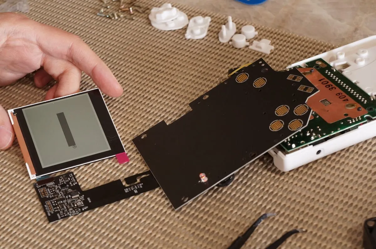
Kit contents
Section titled “Kit contents”Before we start installing this kit, make sure all required parts are present.
Parts included in this kit:
- 1x IPS LCD
- 1x LCD board
- 1x Front PCB (button pad)
- 1x Ribbon cable, large
- 1x Ribbon cable, small
- 1x Adhesive strip
- Tweezers
- Y1 tri-wing screwdriver for the shell screws
- PH1 Phillips screwdriver for the mainboard and inner screws
- Soldering equipment (not needed with the “speaker pre-installed” option)
Preparation
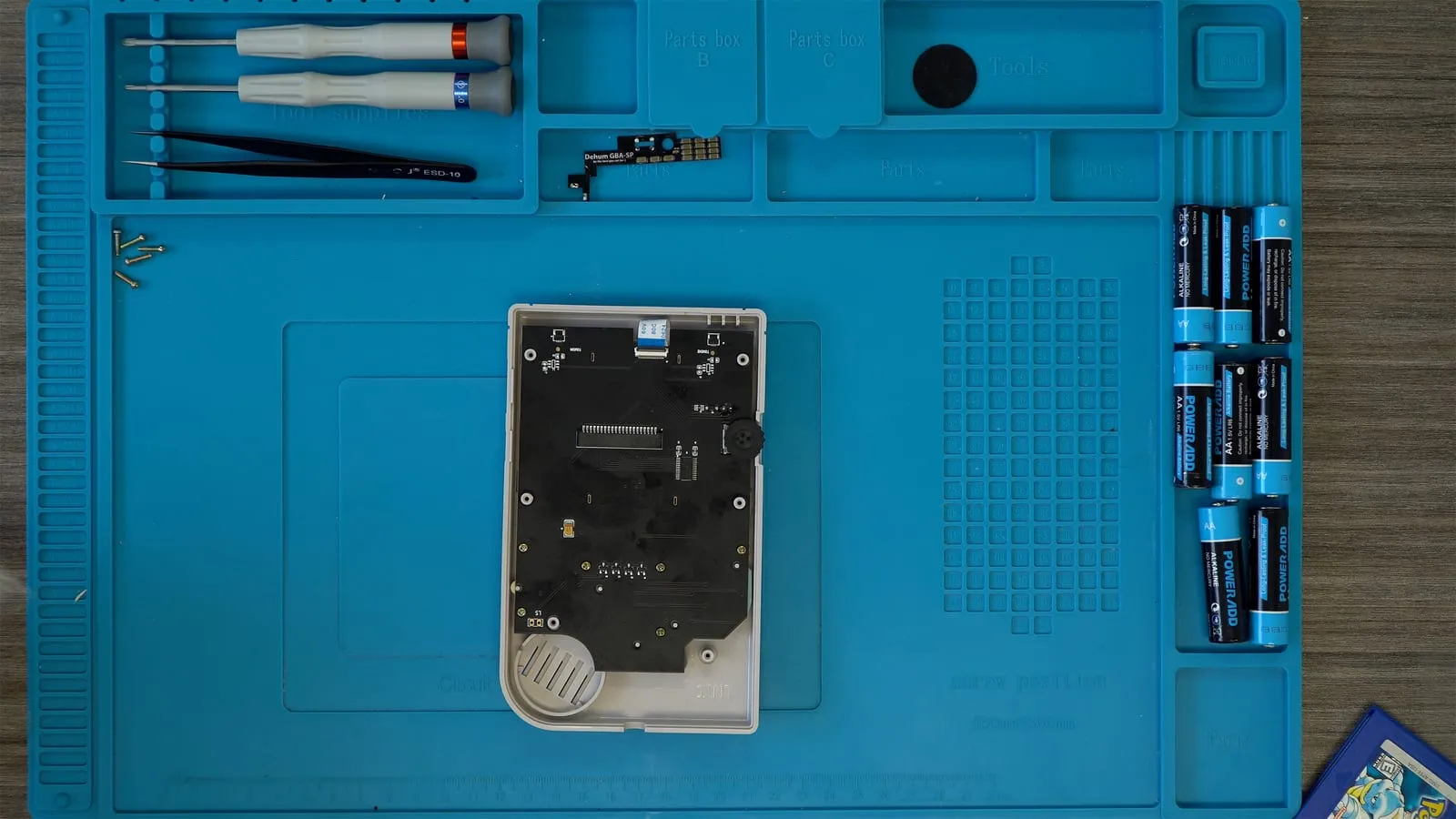
Section titled “Preparation”- Take the Game Boy apart: Disassembling the shell
- Leave the main board in the rear housing. There is no need to remove it.
- If you’re new to soldering, read Hand Held Legend’s Soldering Iron Guide.
- Fully test your IPS kit before installation: How do I test the LCD
Shell modifications
Section titled “Shell modifications”If you have a matching pre-cut shell, you can skip the following steps. You may still need the contrast wheel modifications (see Installation).
For a shell that isn’t pre-cut:
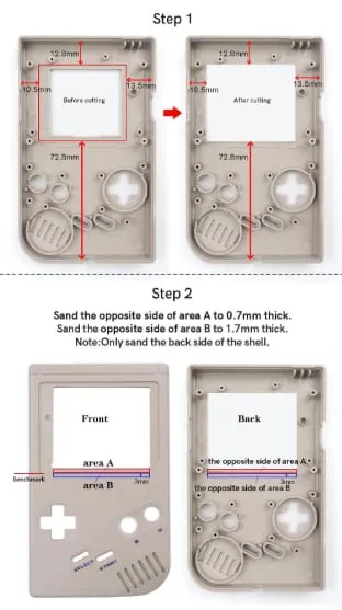
- Cut out the screen opening on the inside of the front shell to the marked dimensions.
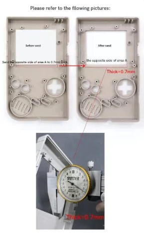
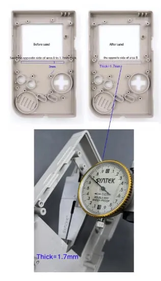
- Sand area A from the back to 0.7 mm thickness and area B from the back to 1.7 mm thickness. Only sand the back side of the shell.
If the console closes too tightly or something doesn’t fit, you can optionally trim this area as well:
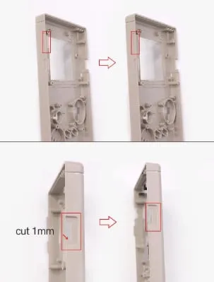
Installation
Section titled “Installation”This overview shows the shell modifications and the installation at a glance:

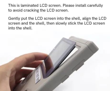
Carefully place the laminated LCD into the shell, align it and slowly press it into place. Take care not to crack the LCD.
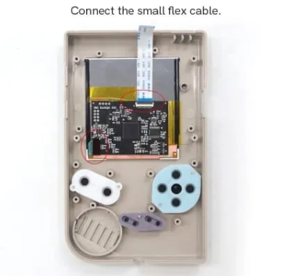
Use the included adhesive strip or Kapton tape to attach the PCB to the back of the LCD panel.
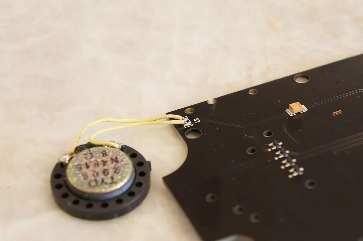
Next, solder the speaker wires to the new IPS control board as shown. Polarity does not matter.
Place your new button PCB on top of the display and connect the ribbon cable before screwing the board down.
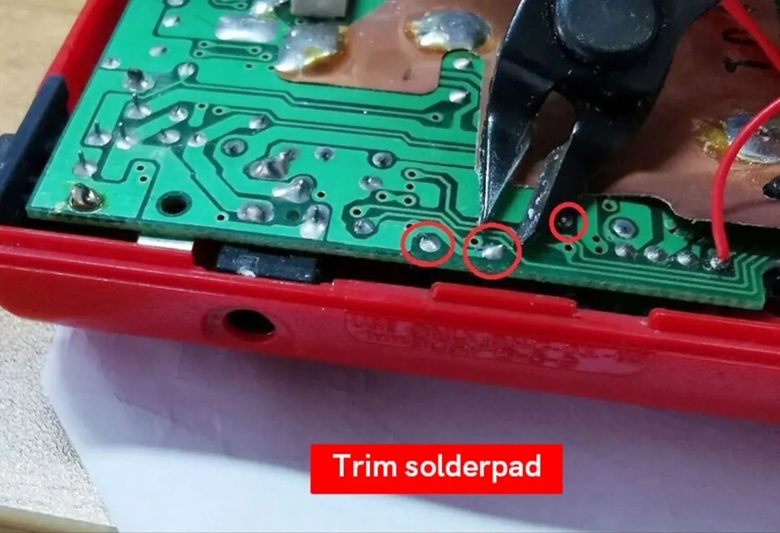
If your contrast wheel is still sticking or binding, trim down these through-hole pins. Cut them and then reflow them so nothing sticks out above the board. You may also want to do the shell modifications in the contrast wheel area described above.
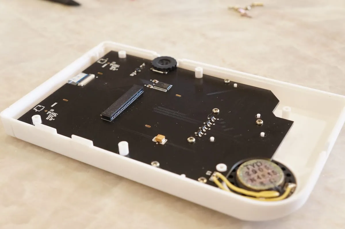
Install the 6 PH1 screws to hold the IPS control board in place.
Plug the larger ribbon cable into the IPS board. This is a pressure-fit connector, so you may need some gentle force to seat the cable properly.
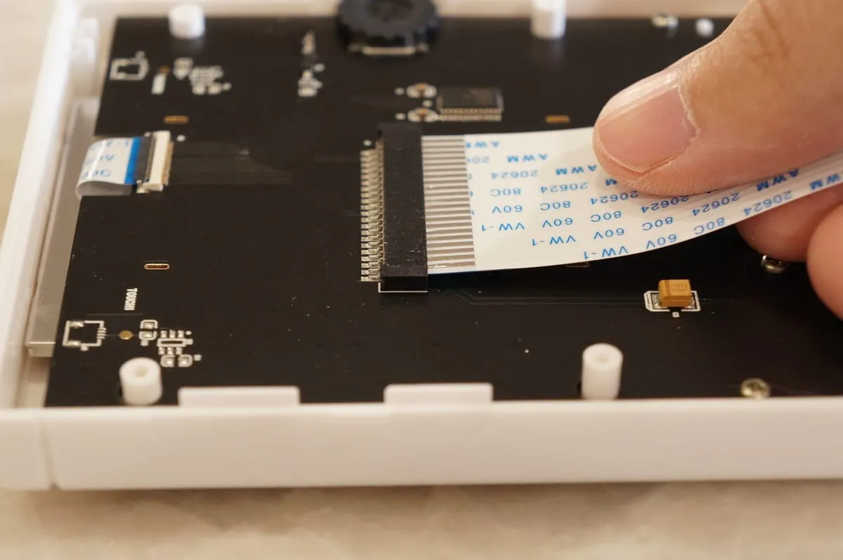
Connect the IPS control board assembly to the main board via the larger end of the ribbon cable.
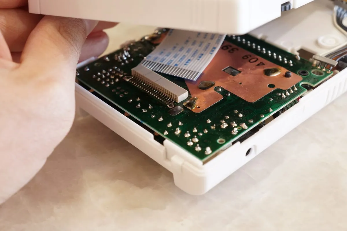
Put the 6 Y1 screws back into the rear housing and close up the console. All done!
Operation
Section titled “Operation”To open the OSD (on-screen display), press and hold the contrast button. Since it has been replaced by the new front board, it now works as a button. Once the OSD is open, you can scroll up and down to navigate the menu. Press the button and scroll to adjust each value.
When you’re not in the OSD, you can change the color selection by pressing the contrast button once.
Troubleshooting
Section titled “Troubleshooting”- IPS Troubleshoot Guide (Hand Held Legend)