
[GBC] Installation Q5 IPS
Foreword
Section titled “Foreword”- Always run a function test , BEFORE you install the IPS kit! Kits that have already been installed cannot be returned under warranty. You can see how to test the kit externally here: How do I test the LCD
- The LCD is very fragile and sensitive to pressure, impacts, etc. Please be especially careful when handling the LCD during installation
Preparation
Section titled “Preparation”The kit includes the following components
To open the shell you need
You can find suitable tool kits here
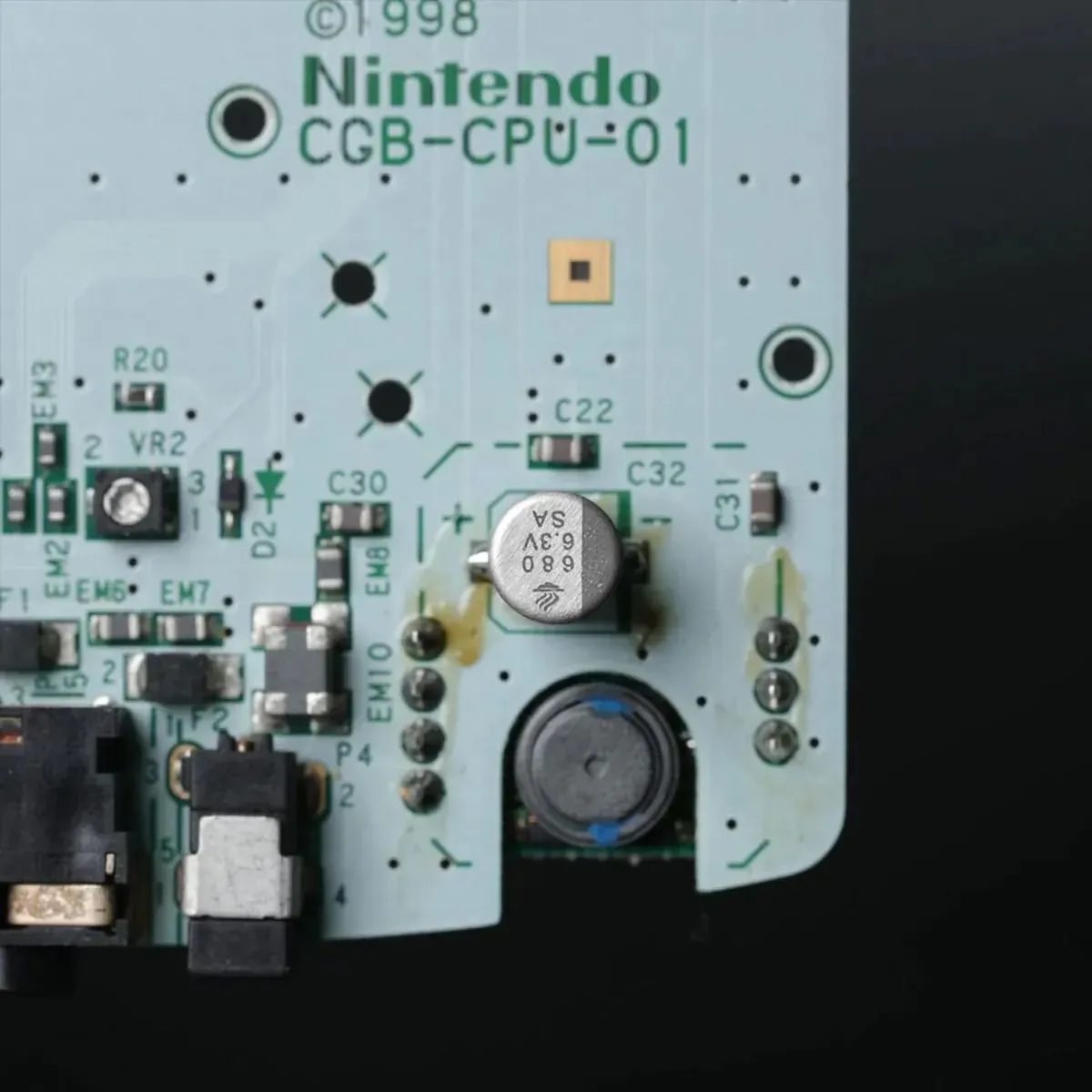
For an LCD mod, the 100uF capacitor should be replaced with a 680uF capacitor to reduce noise.
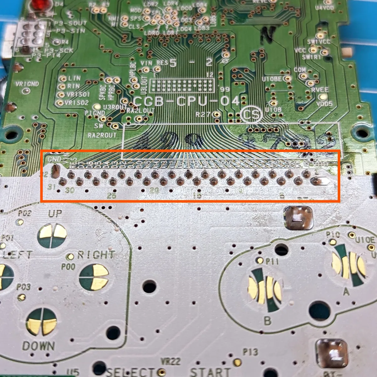
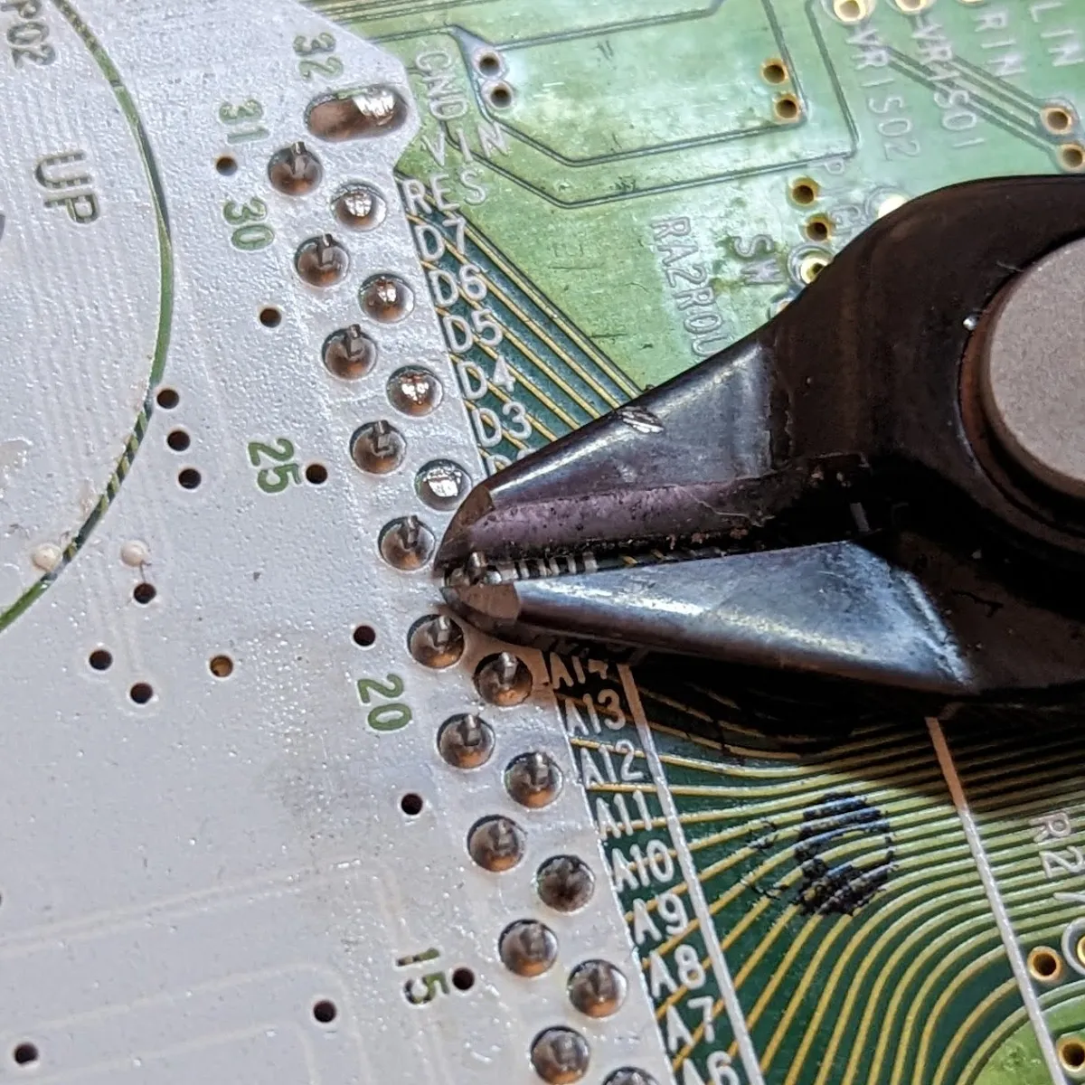
The pins of the cartridge port can press against the LCD, which can cause permanent damage. That’s why the pins have to be trimmed as short as possible with side cutters. Watch out for flying pieces and protect your eyes!
Preparing the shell
Section titled “Preparing the shell”If you are using an original OEM or non-IPS-ready shell, you need to make some modifications so the larger LCD of the Q5 XL kit fits. You can find details here: [GBC] Trimming the Shell
Pre-trimmed or IPS-ready shells can be used without modifications. With RetroSix shells, the pins around the LCD opening have to be removed: [GBC] Trimming the RetroSix Shell
Installation
Section titled “Installation”First, apply the included adhesive tape, which will prevent the LCD from shifting after installation. The area in the middle must be completely covered.
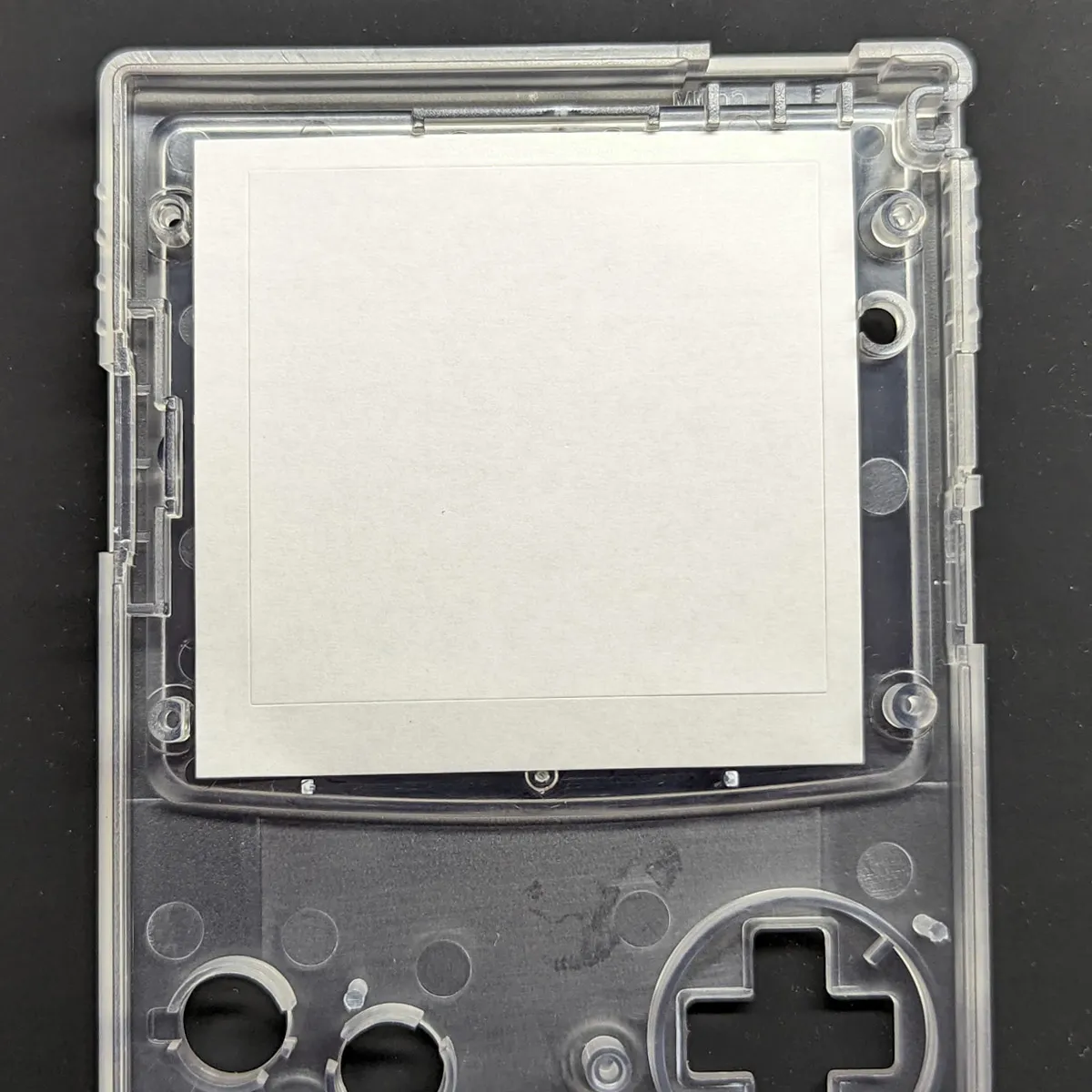
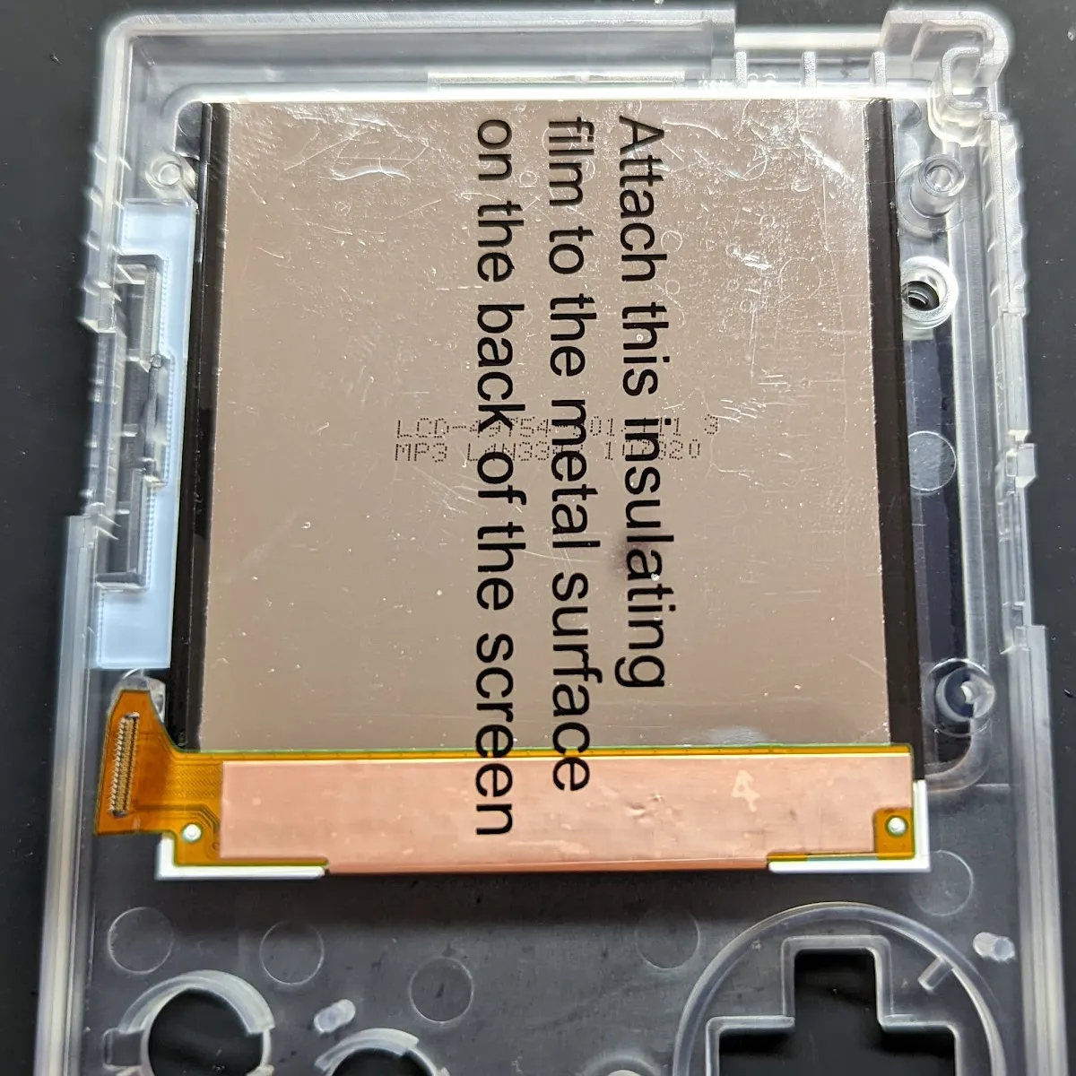
Then remove the protective film and gently place the LCD on top. The large insulation film is stuck to the back of the LCD. Pay attention to the alignment of the display; it should sit straight in the shell. Use nearby shell edges as a reference or use the optionally available positioning frames to help.
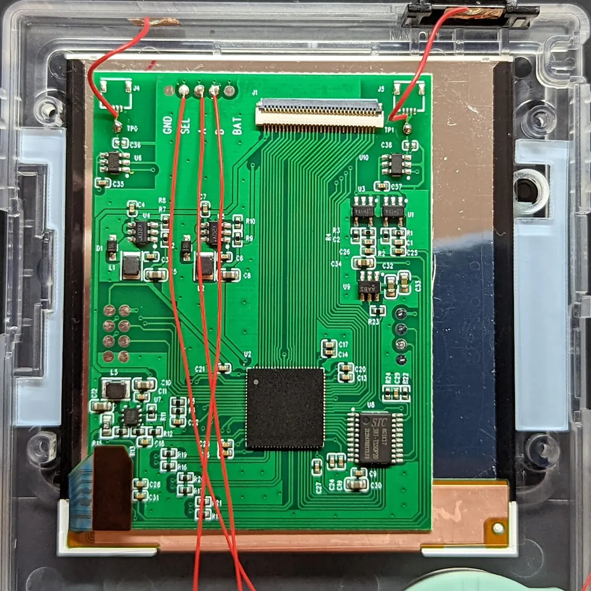
The PCB board is connected to the LCD via the small connector. Careful, do not put any pressure on the LCD! The Q5 IPS kit can be controlled either via touch or via buttons. So that we can operate the OSD functions with the buttons, 3 wires are soldered to the corresponding contacts on the LCD controller, which are later connected to the Game Boy Color mainboard.
The touch sensors are attached to the top of the shell or to the IR cover. Make sure the wires are not routed near the ribbon cable between the PCB and the GBC mainboard - the sensors are sensitive to interference and, when disturbed, trigger constantly or not at all.
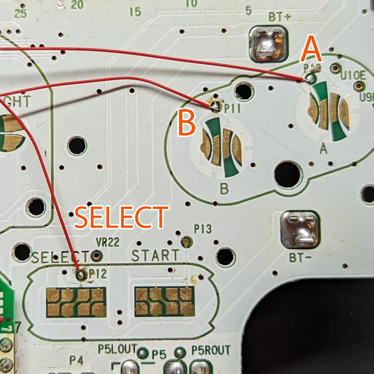
The 3 wires are soldered to the following contacts on the GBC mainboard.
Now connect the PCB to the Game Boy Color mainboard using the included ribbon cable. Make sure you plug it in the right way round.
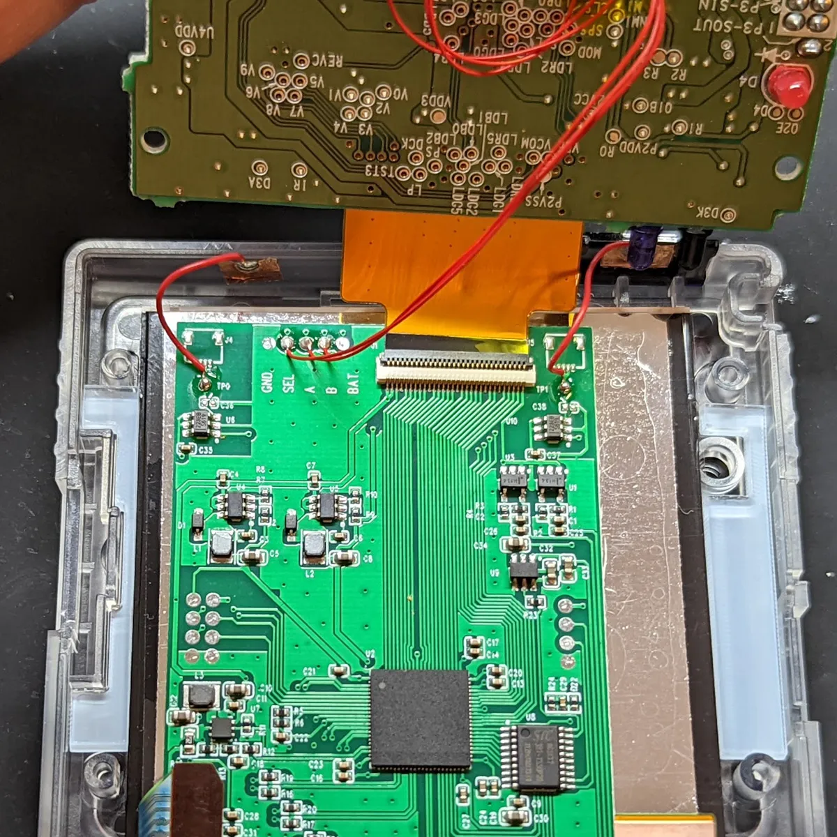
Before inserting the mainboard, place the second included insulation film between the PCB and the mainboard to avoid short circuits later on.
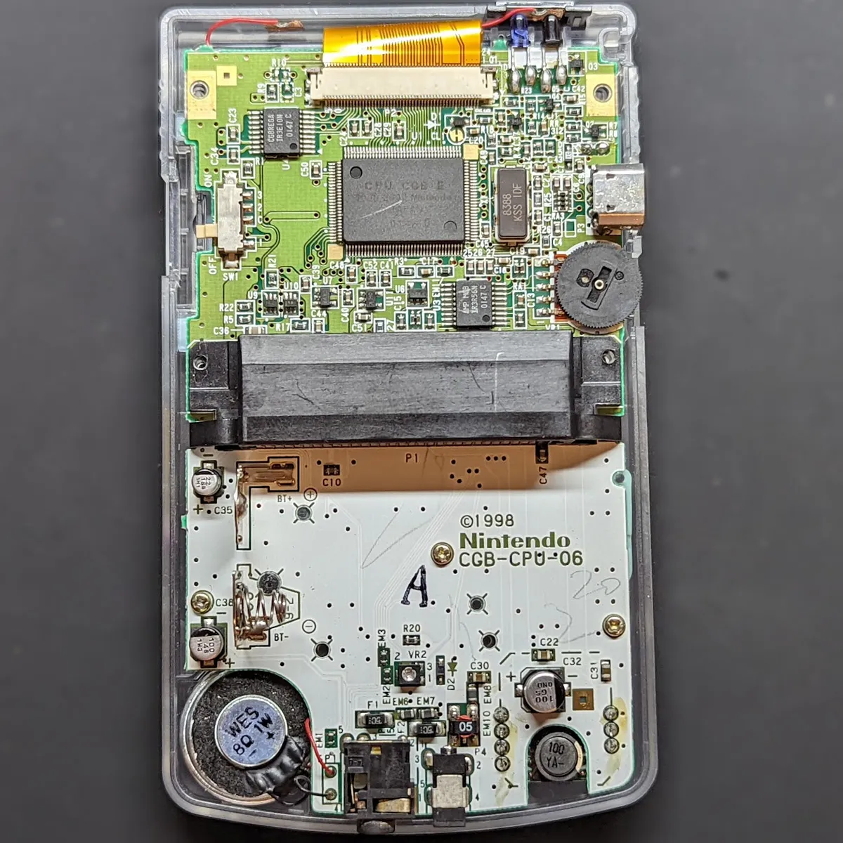
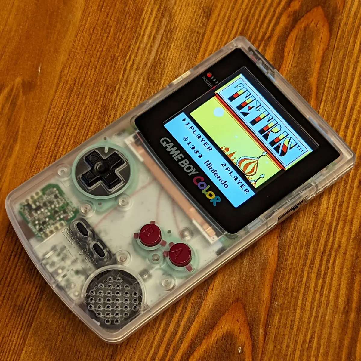
Finally, attach and screw on the back of the shell and install the display glass. To remove dust between the glass and the LCD, use an air blower.
Controls
Section titled “Controls”Sensors:
- Left sensor short press: color palette
- Left sensor long press: pixel effects
- Right sensor short press: brightness
- Right sensor long press: battery indicator on/off
OSD menu:
- Hold Select and press A + B to open the OSD menu
- A and B scroll through the lists
- Select + A activates the current option
- Select + A saves the selection
- Select + A goes back one step
- Holding Select + B closes the OSD menu
Buy the Q5 XL IPS Backlight Mod for GBC at silentmodding.com