
[GBA] RetroSix CleanScreen
The CleanScreen replaces the original Game Boy Advance LCD with a backlit IPS display. It has exactly the same size and pixel size as the original. That’s why it fits the original shell without any changes and works with every original size lens. In True Color mode the colors are matched to the AGS-101. Thanks to TrueMotion, the CleanScreen shows transparency effects like the original LCD, without flicker.
There are two ways to install it:
- Without soldering: drop in the LCD and plug it in. In an original shell this takes a few minutes. The on screen menu (OSD) is not available then, the display runs with its factory settings.
- With the OSD ribbon (recommended): you also solder the included ribbon to three test points on the mainboard. No single wires needed. This gives you the menu for brightness, color mode, pixel grid and screen position. In a RetroSix shell you need the menu to center the picture.
Box contents
Section titled “Box contents”- 1x IPS LCD
- 1x CleanScreen board
- 1x 32 pin and 1x 40 pin connection ribbon
- 1x ribbon for button control (OSD)
- 1x dust guard
- 1x positioning bracket
- 1x tempered glass lens (black)
- Y1 tri-wing screwdriver for the shell screws
- J1 screwdriver for the mainboard screws
- Tweezers
- For the OSD ribbon: soldering iron, solder and flux
- Optional: Kapton tape, flush cutters
32 pin or 40 pin?
Section titled “32 pin or 40 pin?”The Game Boy Advance comes with a 32 pin or a 40 pin LCD connector. The kit includes both ribbons, you only need the matching one. Through the small hole in the battery compartment you can see a number on the mainboard: if it starts with 0 it’s a 40 pin board, if it starts with 1 it’s a 32 pin board. With the shell open, you’ll also find 40 or 32 printed right next to the LCD connector. Details with pictures: [GBA] 32 Pin or 40 Pin?
Removing the old screen
Section titled “Removing the old screen”-
Open the shell: remove the tri-wing screws of the back shell and the Phillips screw in the battery compartment, then take off the back shell. A detailed guide is in [GBA] Shell Disassembly.
-
Remove the mainboard: remove the Phillips screws holding the mainboard (usually three in the middle). Gently push the two tabs of the LCD connector outwards and pull out the ribbon of the old LCD with your fingers or tweezers. Put the mainboard aside.
-
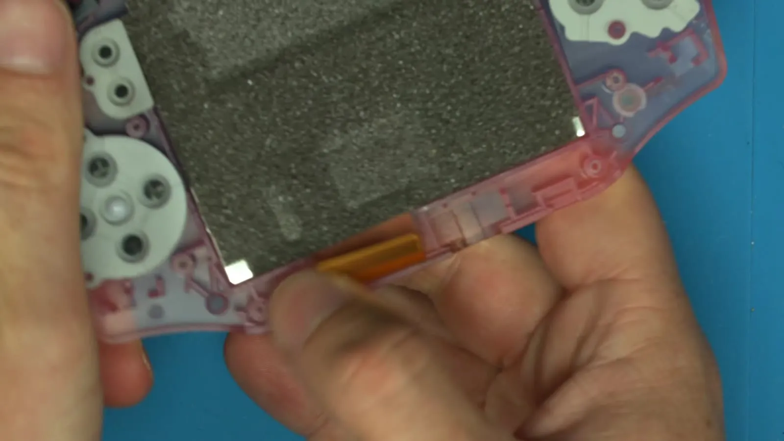
Release the old LCD: carefully twist the LCD a little to the left and right until the adhesive lets go with an audible click. Then lift it out.
-
Remove the old gasket: the original adhesive strip around the window usually comes out with the LCD. Use the included dust guard instead (next section). A gasket that is sticky on both sides is a bad idea: the LCD gets stuck and is hard to remove later.
Lens and dust guard
Section titled “Lens and dust guard”The dust guard seals the gap between shell and LCD. The lens protects from the outside, the dust guard from the inside. Once assembled, no more dust gets under the lens. It is only sticky on one side: that side goes onto the shell, the LCD just presses against the other side. That way you can still remove the display at any time.
-
Fit the lens: place the included lens (or any other original size lens) into the recess on the outside of the front shell. Lenses with an enlarged viewing area made for other IPS kits are not recommended.
-
Stick on the dust guard: peel the backing off the adhesive side and stick the dust guard to the inside of the front shell so that it surrounds the screen window all the way round. Press it down firmly all around.
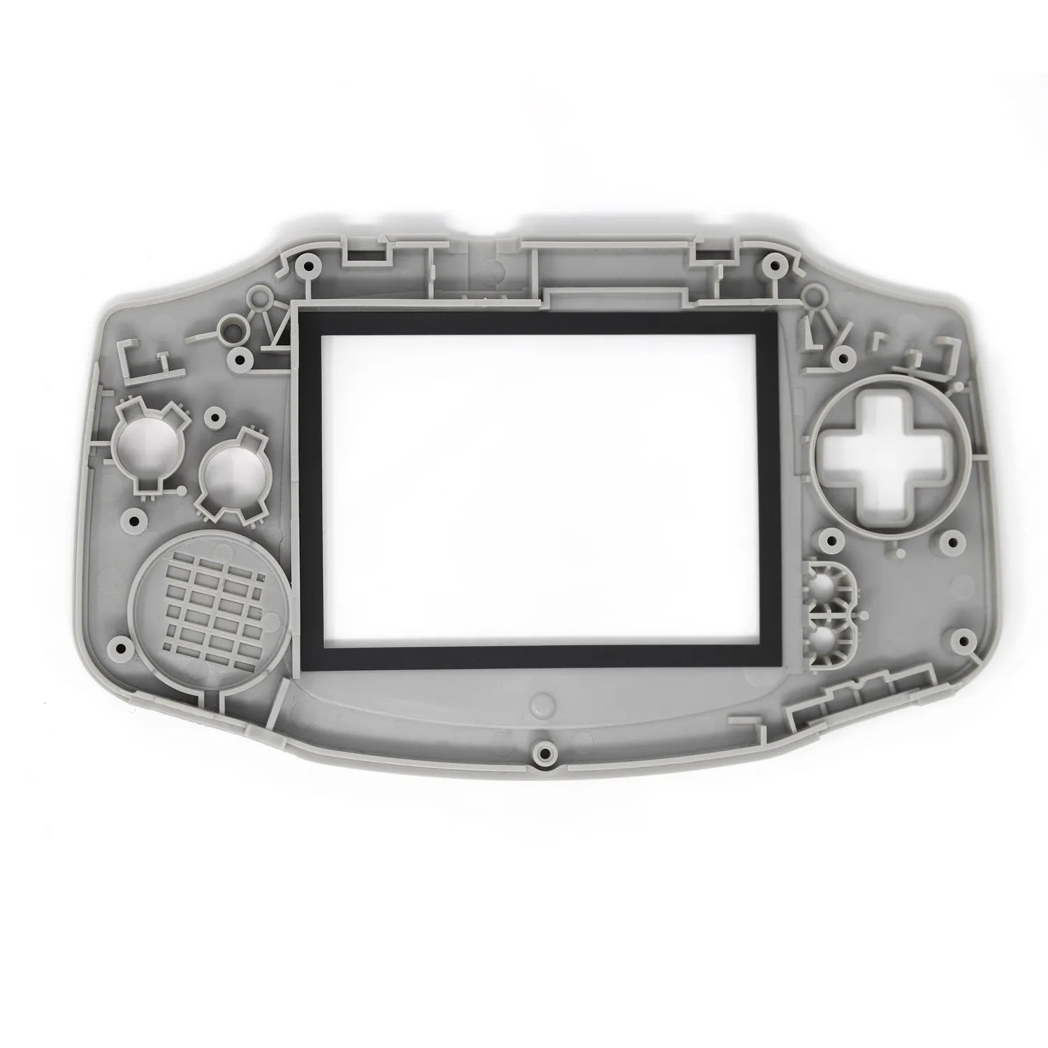
Then fit the LCD as described below. The LCD rests directly on the dust guard.
Installing in an original shell (no soldering)
Section titled “Installing in an original shell (no soldering)”In an original shell you don’t need the bracket or any tape. The LCD fits the shell exactly.
-
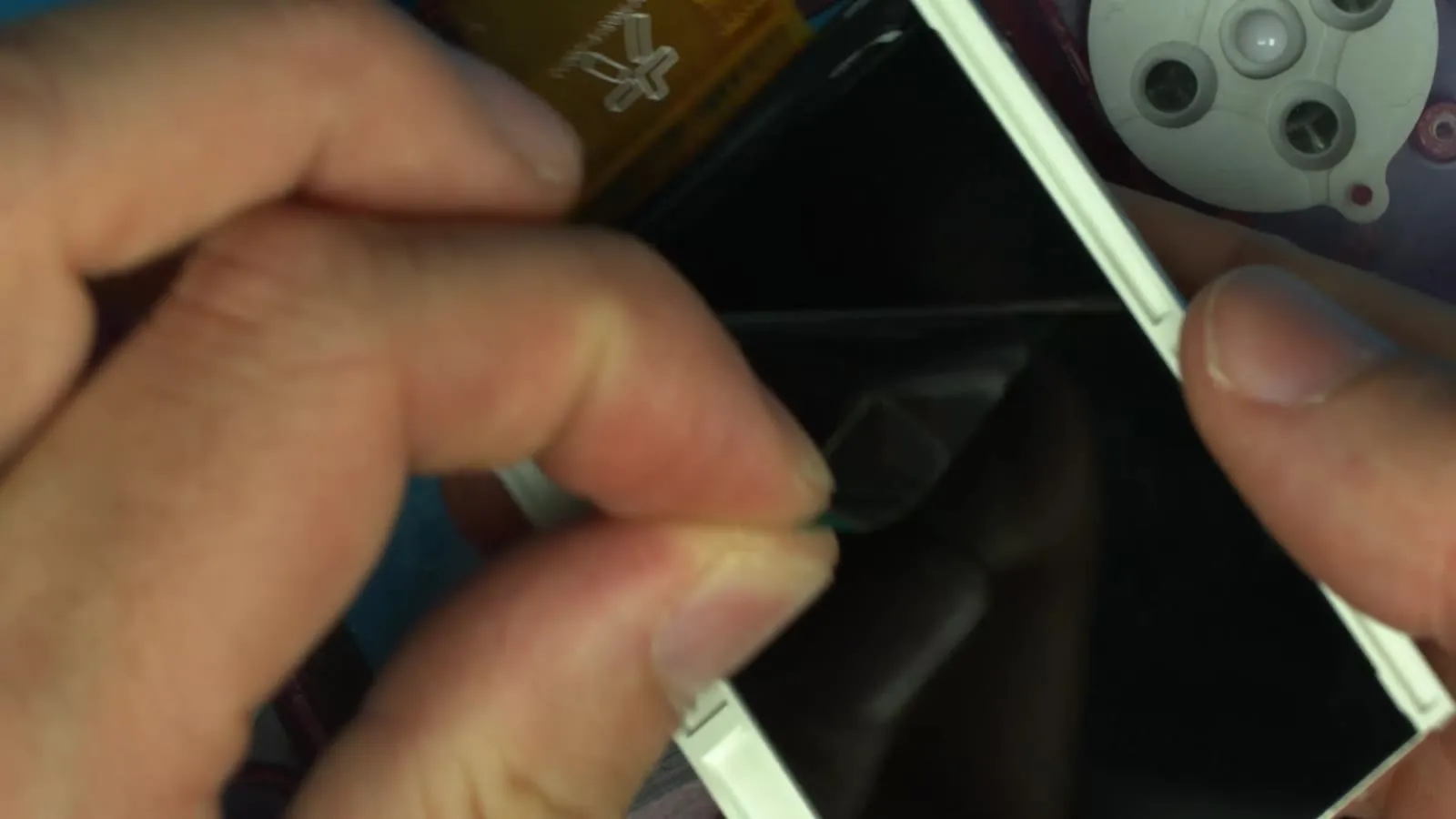
Peel off the protective film: remove the protective film from the front of the new LCD. The display has a matte finish that reflects less and is easy to clean. The LCD ribbon has a reinforcement strip that protects the delicate area from tearing.
-
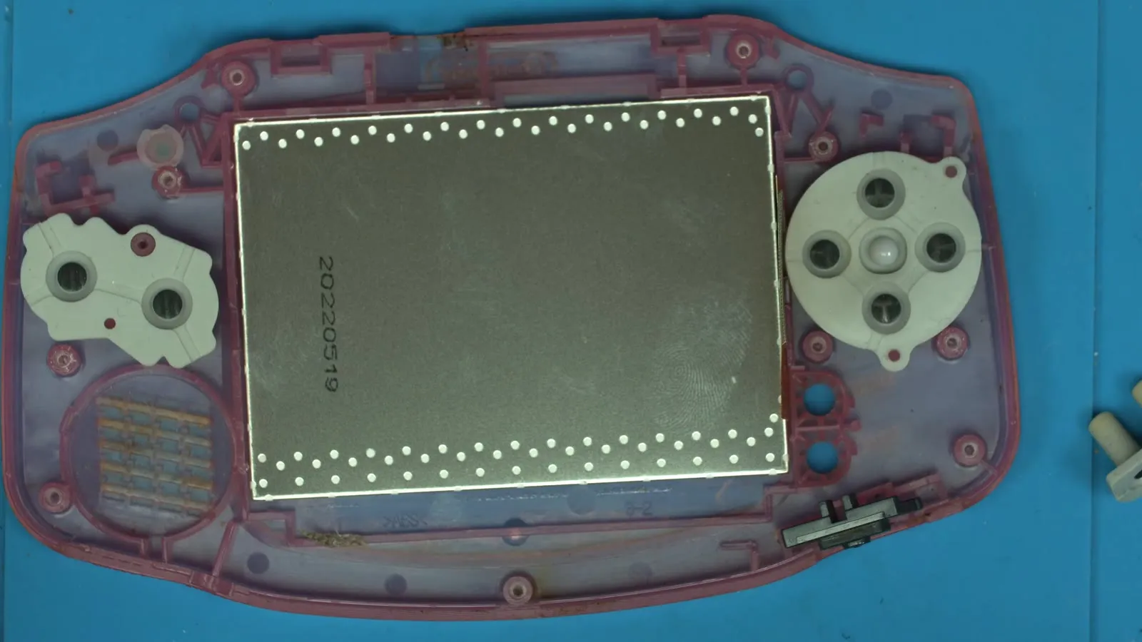
Fit the LCD: first take out the Start/Select rubber, otherwise it gets in the way of the ribbon. Place the LCD in the recess and push it down. It’s a snug fit.
-
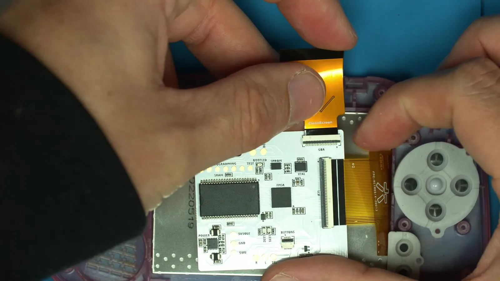
Connect the LCD to the board: flip up the latch on the connector of the CleanScreen board. Insert the LCD ribbon until the end of the reinforcement strip lines up with the edge of the board. Flip the latch back down. The board simply rests on the LCD and doesn’t need fixing.
-
Refit the buttons: put the Start/Select rubber and the power switch slider back in.
-
Plug in the connection ribbon: take the matching ribbon (32 or 40 pin). Flip up the second latch on the CleanScreen board, insert the end labelled “CleanScreen” with the black side up and flip the latch down.
-
Refit the mainboard: put the mainboard back into the shell. Make sure the power switch engages with the slider. Screw the mainboard screws back in.
-
Connect the ribbon to the mainboard: fold the connection ribbon over, slide it into the LCD connector of the mainboard and push the two tabs on the left and right closed.
-
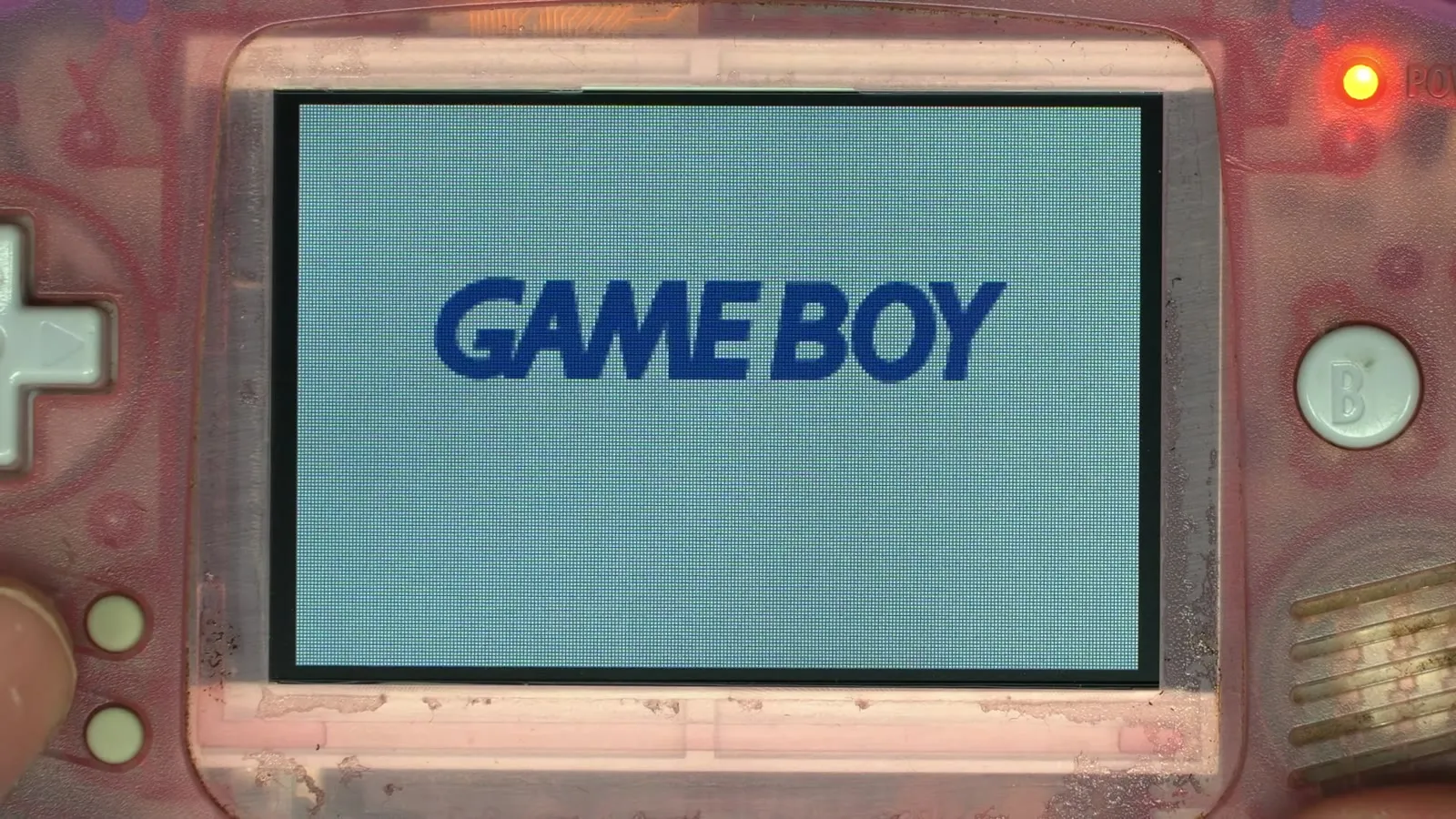
Close the shell: fit the back shell, screw it together, insert batteries and switch the Game Boy on.
Installing with the OSD ribbon and bracket
Section titled “Installing with the OSD ribbon and bracket”This is how you install the CleanScreen with the on screen menu in a RetroSix shell (or another IPS ready shell). The OSD ribbon works the same way in an original shell, just leave out the bracket there.
Soldering the OSD ribbon
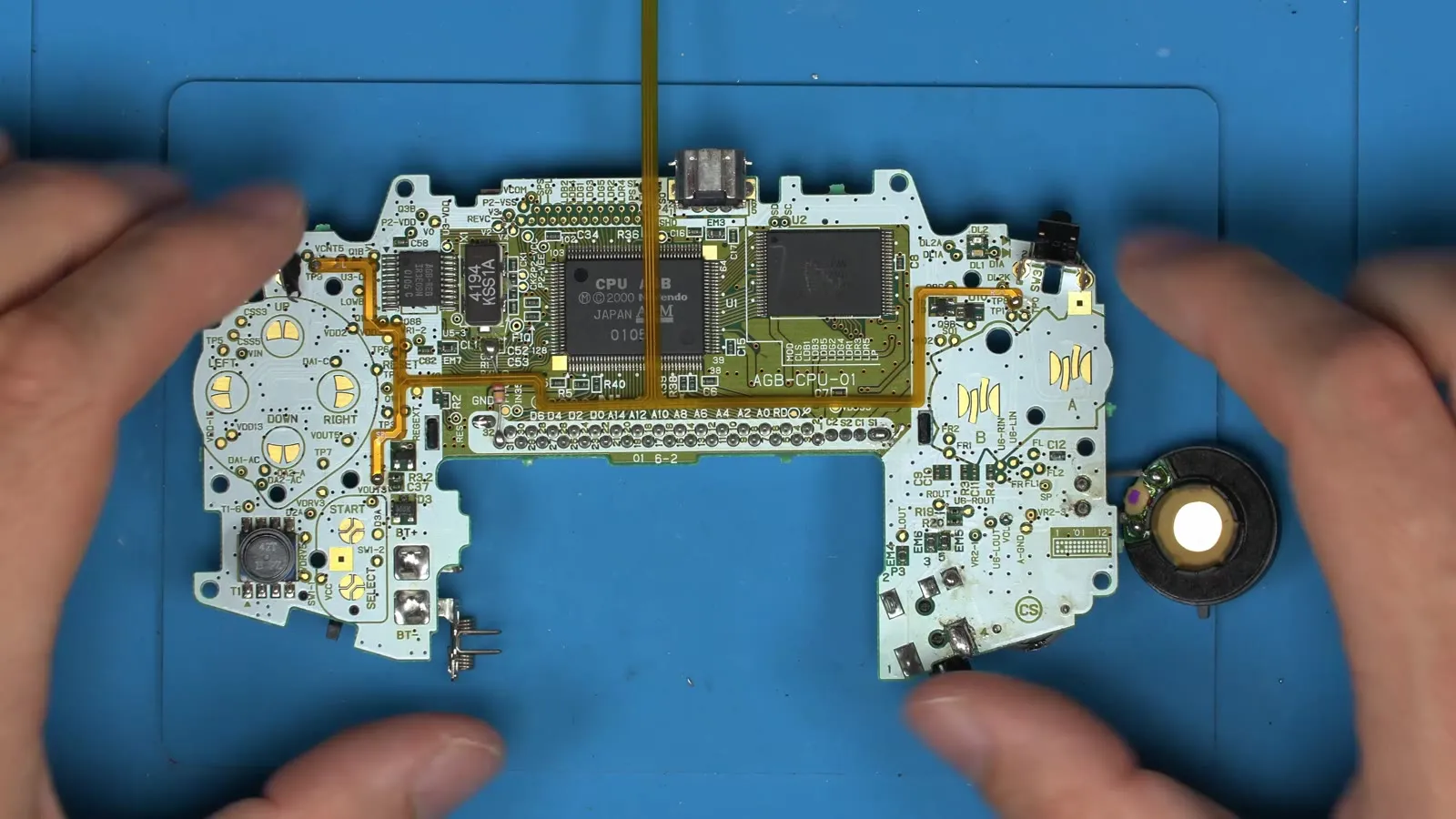
Section titled “Soldering the OSD ribbon”The ribbon connects three button test points on the mainboard (TP2, TP9 and TP8 in the video) to the CleanScreen board. It is shaped so that its three solder eyes sit exactly on these test points. You only solder it once. After that you can swap shell, board and display at any time without soldering.
-
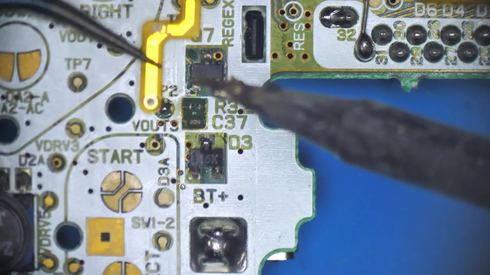
Tin and solder TP2: tin test point TP2 with a little solder and flux. Place the solder eye of the ribbon on the point, hold it down with tweezers and tack it with a little solder on the iron tip through the hole in the solder eye.
-
TP9 and TP8: do the same on the other two test points: tin the pad, press the ribbon down, tack it in place. Afterwards check that there are no solder bridges to neighbouring pads.
Fitting the display with the bracket
Section titled “Fitting the display with the bracket”-
Prepare the shell: fit the D-pad, the A/B buttons, the rubbers and the power LED light pipe into the front shell. The lens and dust guard are already in (see above).
-
Check the bracket: older brackets still have an extra arm for third party IPS screens. This arm reaches into the area of the CleanScreen board. Cut it off flush at the last dimple with flush cutters. Without this arm, the bracket fits as it is.
-
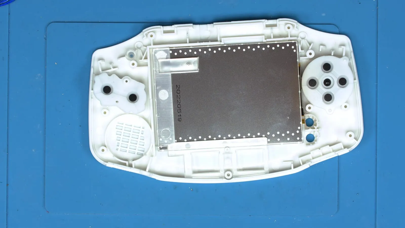
Fit the LCD: place the LCD into the window and push it into the top right corner (seen from the inside).
-
Fit the bracket: place the bracket into the gap next to the LCD. It holds the display in position without pressing on it too hard. The display always sits in the same spot, and there’s no light bleed from pressure.
▶ Watch in the video from 5:03
Without the bracket, push the LCD into the top right corner as well and secure it with tape or glue.
-
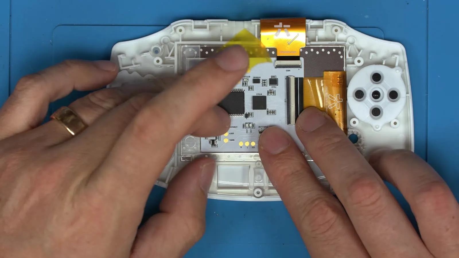
Connect the board: connect the LCD to the CleanScreen board as described above. The board fits exactly into the cut-out of the bracket. A small piece of Kapton tape stops the board from moving around during assembly. This is optional.
-
Fit the rubbers: put in the Start/Select rubber and plug the connection ribbon (32 or 40 pin) into the CleanScreen board.
Connecting the mainboard and closing the shell
Section titled “Connecting the mainboard and closing the shell”-
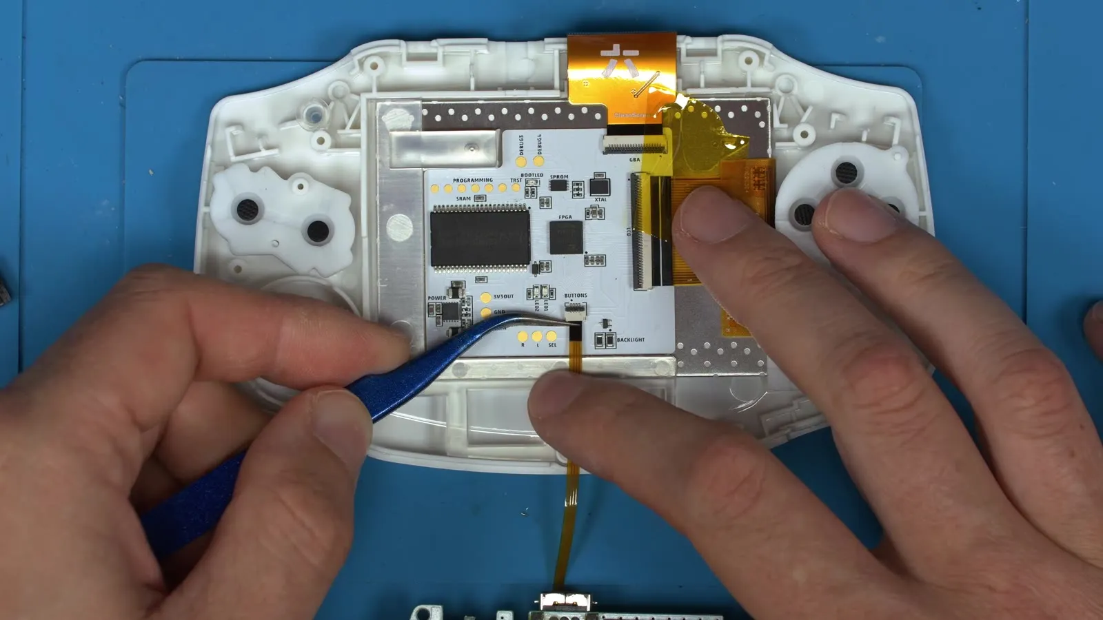
Plug in the button ribbon: turn the mainboard over, the way it’s about to go into the shell. Plug the OSD ribbon into its connector on the CleanScreen board, then fold the mainboard over. If you use wires instead of the ribbon, solder them directly to the Select, L and R pads.
-
Screw down the mainboard: screw in the mainboard screws, plug the connection ribbon into the LCD connector of the mainboard and fit the shoulder buttons.
-
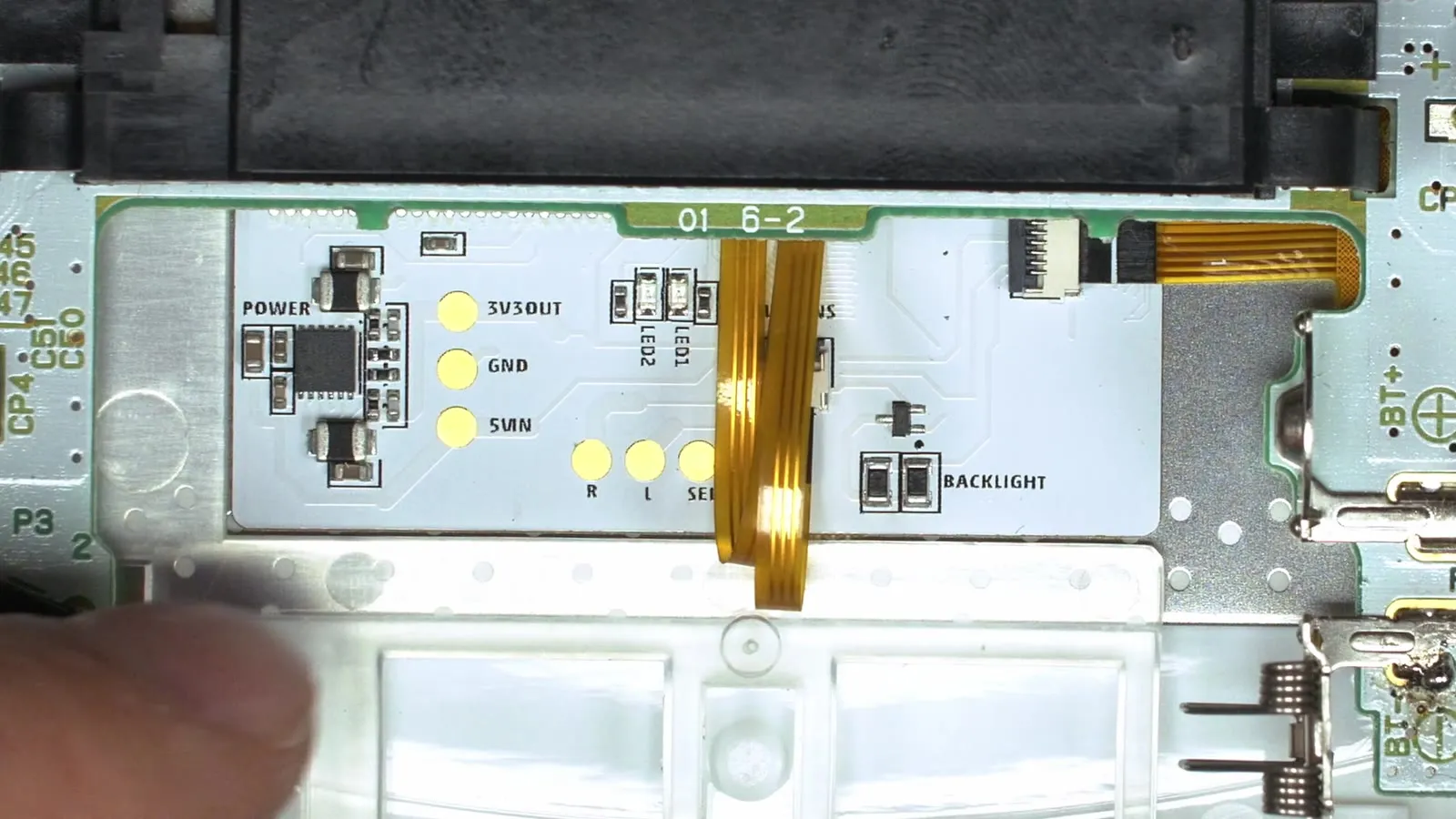
Fold the ribbon: fold the excess part of the OSD ribbon over twice and tuck it under the mainboard near the battery compartment. Nothing presses on it there. When you fit the back shell, the ribbon lies flat without kinking. This way you can unscrew the mainboard later without tearing a ribbon.
-
Close the shell: fit the back shell and screw it together.
On screen menu (OSD)
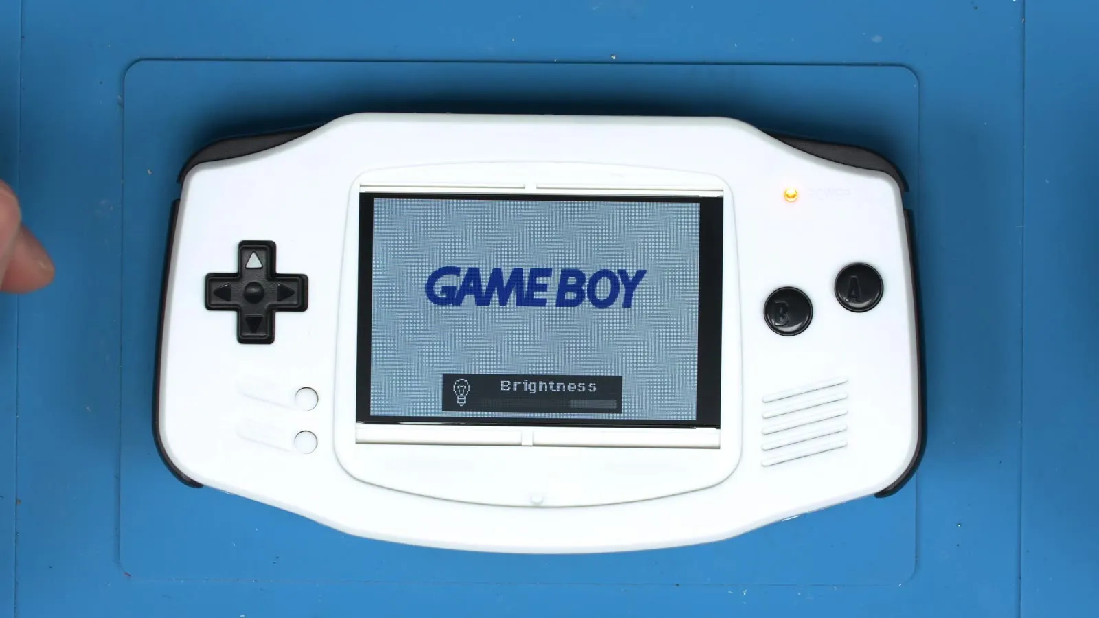
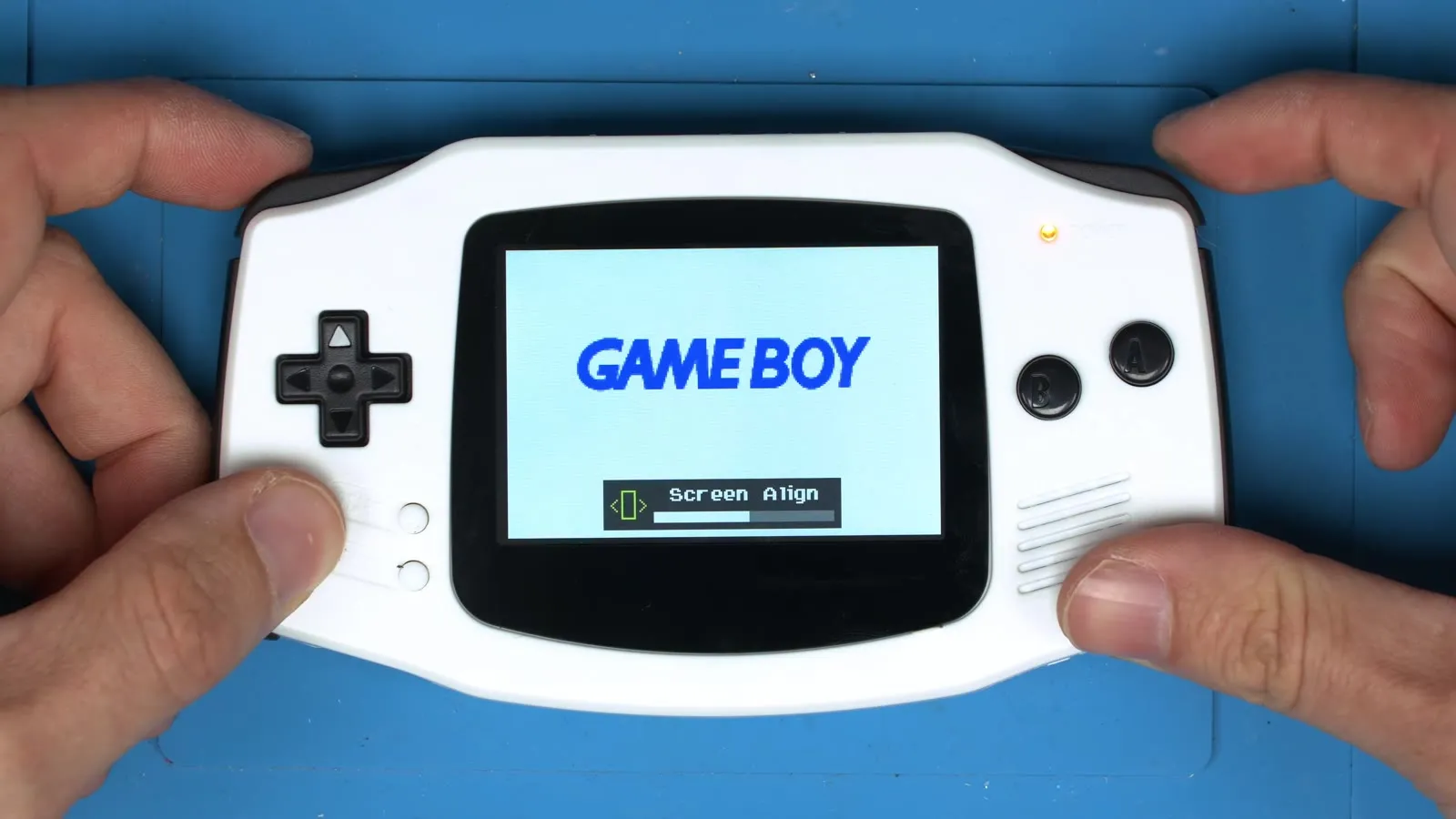
Section titled “On screen menu (OSD)”Hold Select + L + R for a few seconds and the menu appears at the bottom of the screen. You operate it with L, R and Select, as only these three buttons are connected to the board. If you don’t press anything for about four seconds, the menu disappears again.
▶ Watch in the video from 8:24
- Brightness: brightness without steps, from very dark to full (around 300 levels).
- Pixel Grid: switch the pixel grid like on the original LCD on or off.
- Color Mode: True Color (colors like the AGS-101), IPS (stronger, oversaturated colors like other IPS kits), black and white, and DMG (colors of the original Game Boy).
- Screen Align: move the picture left or right. In a RetroSix shell with bracket the LCD sits further over than in an original shell. This is where you center the picture pixel perfect in the window.
- True Motion: games create transparency by switching graphics on and off every other frame. With True Motion you see them transparent like on the original instead of flickering.
▶ Watch in the video from 9:31
All settings are kept after switching off. Out of the box it is set to True Color with pixel grid and about 60 % brightness.
Videos
Section titled “Videos”Installation in an original shell without soldering:
Installation with OSD ribbon and bracket in a RetroSix shell: