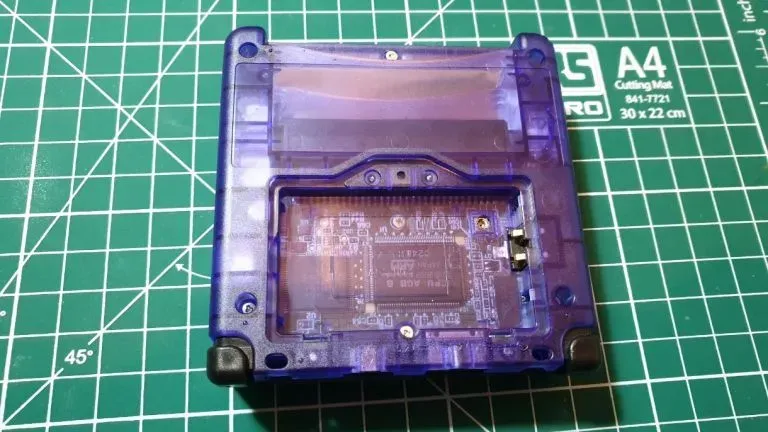
[GBASP] V2 IPS LCD by Hispeedido
This guide was kindly provided by our friends at HandHeldLegend.com.
Installation
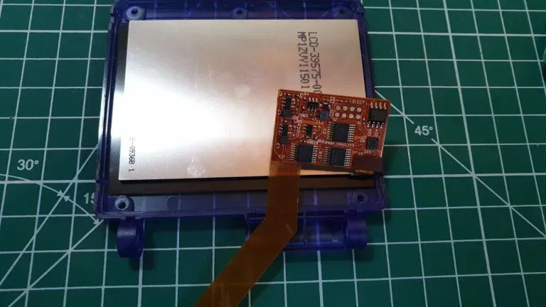
Section titled “Installation”Connect the ribbon cable to the connector on the back of the screen. Once the cable is connected, fold the ribbon cable back as shown in the picture below. You can also secure it to the back of the screen with a bit of tape if you like.
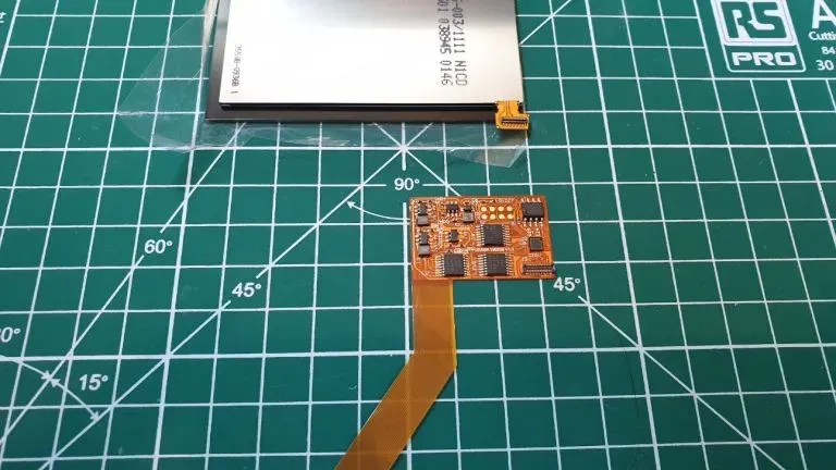
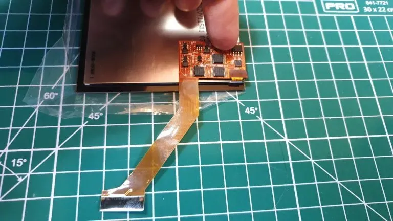
Once the ribbon cable is installed, you should test the screen before continuing. Connect the ribbon cable to the connector on the main board and hold the battery in place to run the test.
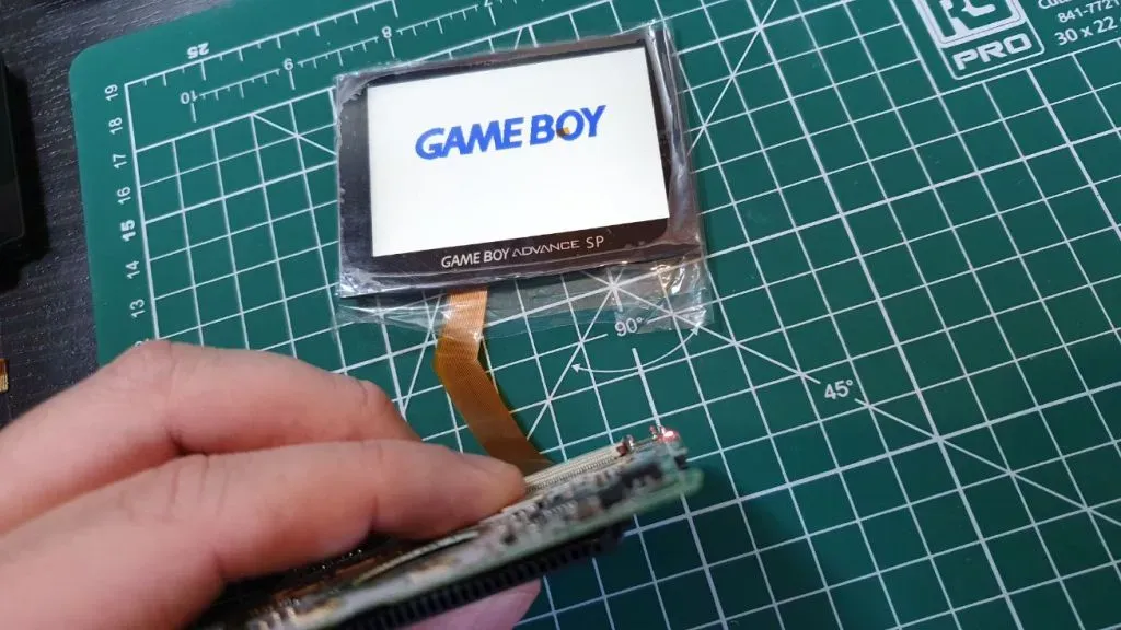
If you bought an IPS-ready shell, no changes to the shell are needed. However, if you have a non-IPS-ready or OEM shell, you’ll need to modify it to fit the IPS LCD. The inside of the shell has to be modified slightly so that it closes with the new screen and the installed ribbon cable.
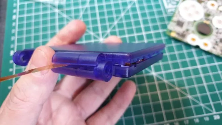
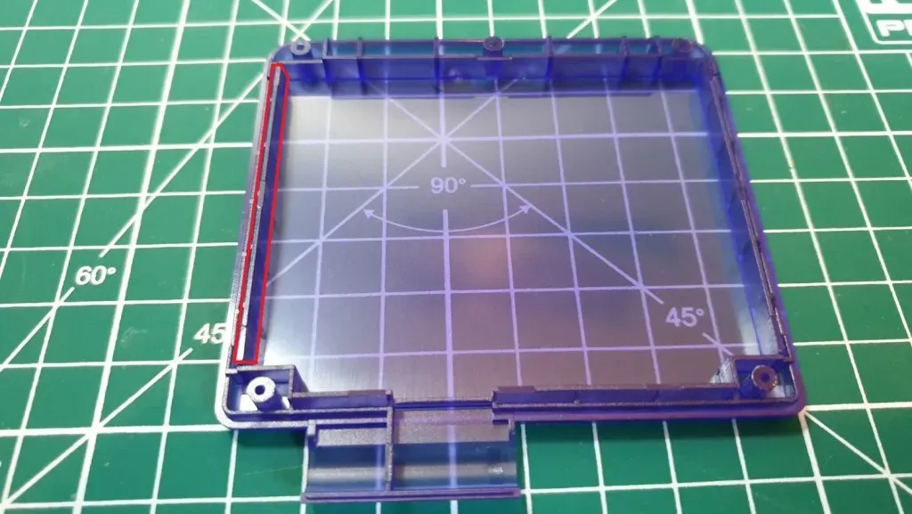
We need to trim the inside of the shell at the spots marked in the image below. You can use a rotary tool like a Dremel, or simply a pair of flat-nose pliers and a utility knife. Remove the marked area to create enough room for the shell to close.
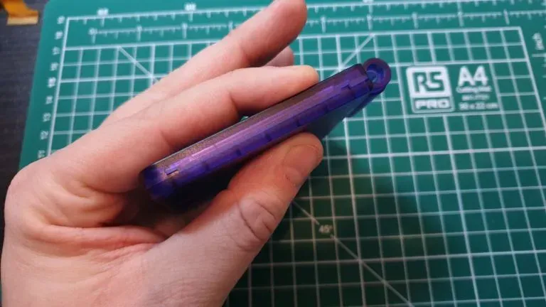
Now we can put the two shell halves together. The IPS kit includes a foam insert that you should place behind the screen to keep the screen and ribbon cable from sliding around. You should also bend the ribbon cable so it doesn’t get pinched in the shell.
Then screw the two halves back together with the screws we removed earlier (you can find suitable screwdrivers here).
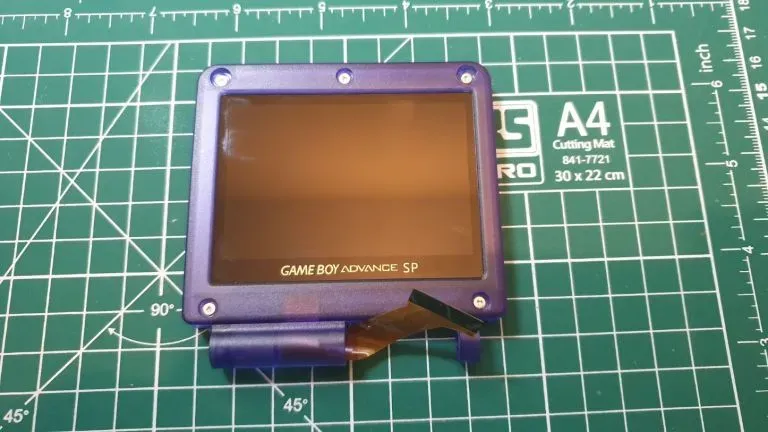
Now we can connect the screen half of the shell to the bottom half. Line it up properly and feed the ribbon cable through the slot provided for it. Next, take the hinges and slide the new caps onto them. Hold the two halves of the shell together while you reinstall the hinges.
Don’t forget to screw in the small Phillips screw to secure the hinge cover.
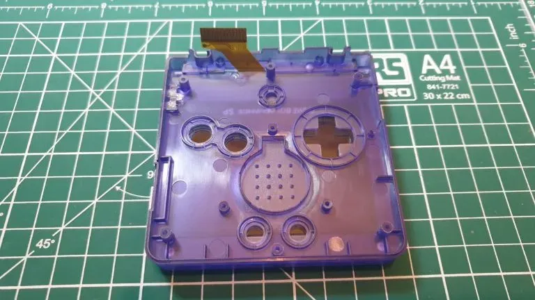
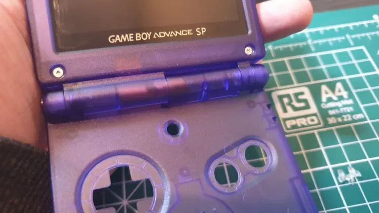
Connect the ribbon cable to the main board and pull the latch down on both sides to lock it securely in place.
Now we’ll solder on the included wire so you can control the brightness (optional).
Solder from point Q12B to the corresponding point on the ribbon cable. Apply some flux to the solder points; you only need a small amount of solder. You can tin the wire beforehand with a bit of flux and solder to make the job easier. Once everything is prepped, touch the solder points with your hot soldering iron.
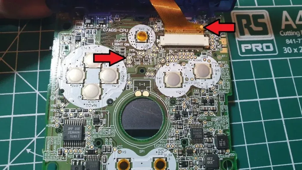
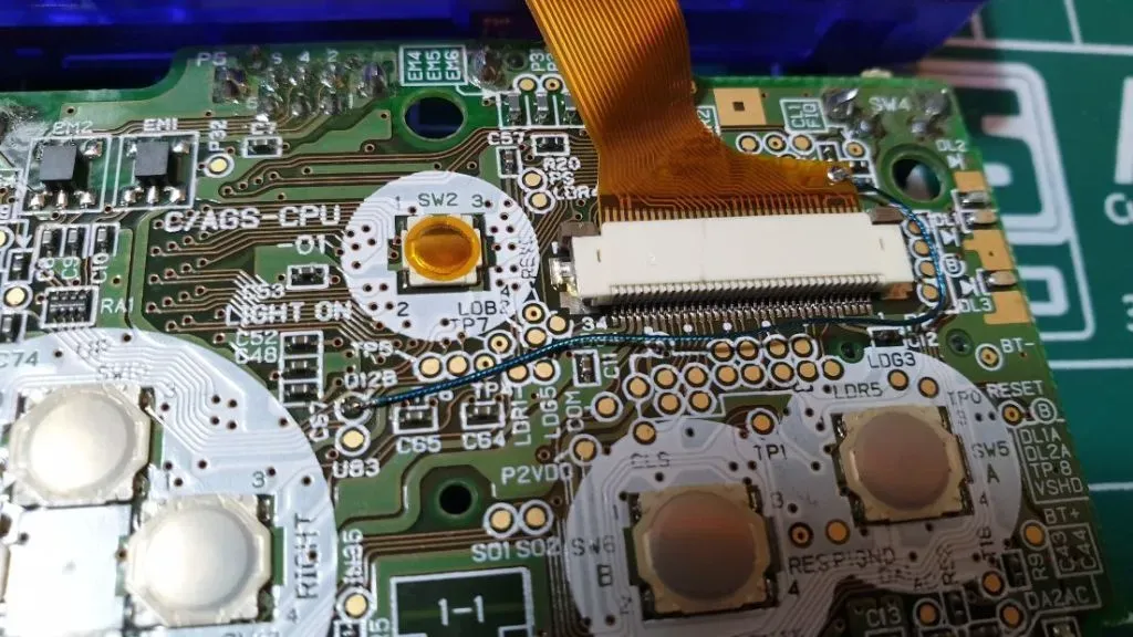
Make sure the wire doesn’t hang over the areas where the button pads go.
Now we can put all the buttons, rubber pads and the speaker back in place. You may also need to line up the volume slider and the power switch. Once everything is in place, we can put the main board back into the shell. With the board seated in the shell, you can secure it with the 3 Phillips screws you removed earlier.
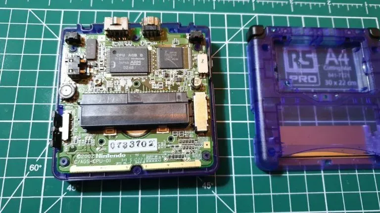
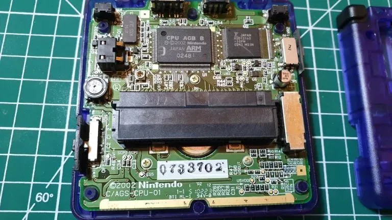
Find the small square washer that fits into the back of the shell. Without this washer, we wouldn’t be able to screw the battery compartment together. Press it into place, and then we can reassemble the GBA SP.
Put back all the screws we removed, and don’t forget the rubber pads around the screen bezel – they simply press into place.