
Installing a PAM8302A Audio Amp (GBA/GBC)
Installing the PAM8302A audio amplifier is a sure-fire way to boost your console’s volume to a level that rivals today’s devices, but it’s not without its challenges. Most notably, how much current the amplifier draws depends on several variables, so you need some background knowledge to make sure you won’t overwhelm the console.
Game Boy Advance
Section titled “Game Boy Advance”Before getting started
Section titled “Before getting started”It helps to know the current draw of your existing mods so you can judge whether this amp will overwhelm your system. The current draw of the PAM8302A depends on several factors, including supply voltage. See the datasheet, page 5, for details.
Parts and materials
Section titled “Parts and materials”- PAM8302A amplifier module
- 2 watt 23 mm speaker
- Hookup wire
- Flux
- Desoldering wick
- 3M VHB (thin) or other double-sided tape
- Multimeter
Mod overview
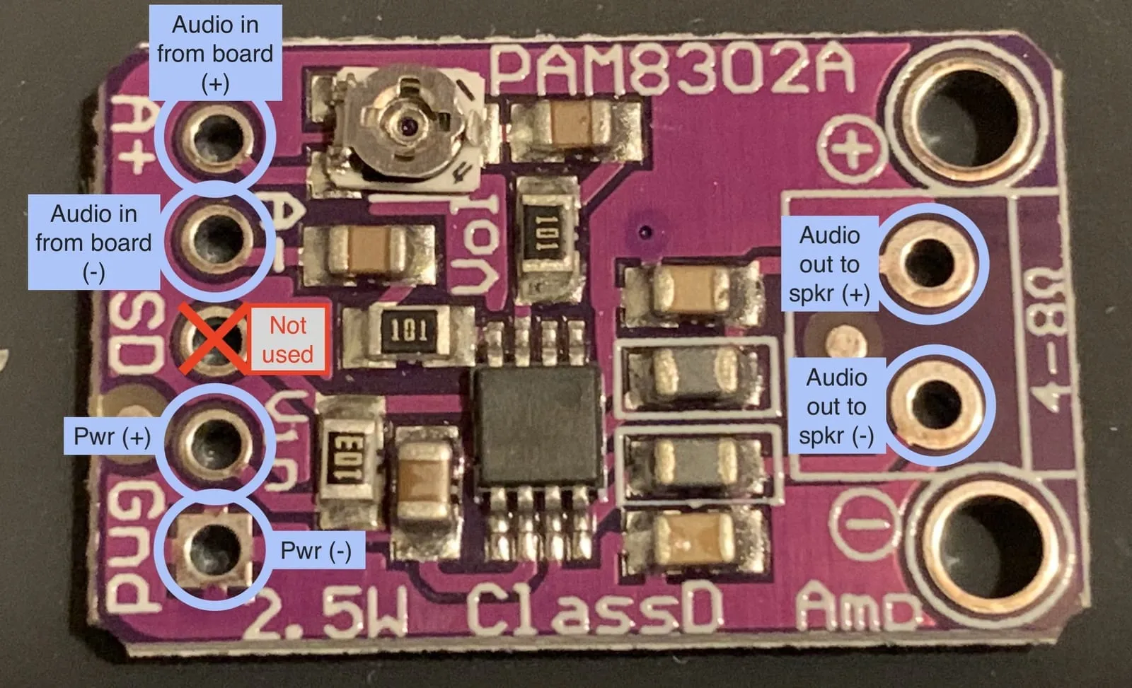
Section titled “Mod overview”The PAM8302A has 7 solder points, and they’re all straightforward. Here’s a diagram:
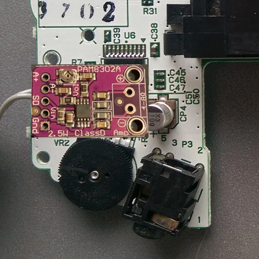
A very convenient spot for the 8302A is on the Game Boy Advance board just above the volume dial. The following mockup shows the placement of the module:
The diagram below shows which connections on the main board you’ll use for this install.
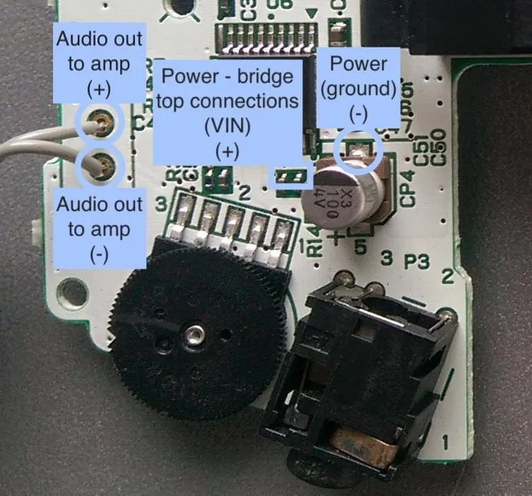
What has proven helpful is to attach the wires to the amplifier first, leaving “just enough” wire on each point to reach the board points shown above.
Basic installation
Section titled “Basic installation”- With the console still assembled, power it on to make sure everything works. Turn the volume all the way up and make sure you hear the startup chime. If everything works, continue.
- Desolder the speaker from the main board
- Use desoldering wick to desolder the two points where the speaker wires connect to the main board. Desolder the wires from the stock speaker as well, you won’t need it once you’re done.
- As shown in the diagram, just left of capacitor CP4, add a touch of solder to join just the tops of the two points, you won’t need much. This is your positive (+) connection point.
- Capacitor CP4 has its negative connection at the top. Add flux and a touch of solder here as well. This will be your ground (-) connection.
- Next up is the PAM8302A itself. Use “just enough” hookup wire so you can work with the PAM8302A board and the connections underneath it. About four inches (10 cm) should be enough without being excessive once the installation is done.
- Power the board
- Solder the wire from VIN on the PAM8302A to the positive (+) point you prepared on the GBA board.
- Solder the wire from GND on the PAM8302A to the top of capacitor CP4, as shown in the board diagram.
- Feed audio to the board
- On the left side of the PAM8302A, wire A+ to the top connection of SP1 (the audio output).
- Also on the left side, wire A- to the bottom connection of SP1.
- Connect the PAM8302A output to the 2 watt 23 mm speaker
- On the right side of the PAM8302A, solder + (amplified audio out) to one of the speaker terminals.
- Also on the right side, solder - (amplified audio out) to the other speaker terminal.
- Note: speaker polarity doesn’t matter for this installation, it works either way. If your speaker has marked + and - terminals, follow them; otherwise just make sure + and - aren’t wired to the same point.
- Test it!
- Before insulating the board and connections, test that everything works. Put the console back together without screwing it shut so you can insert batteries. Turn the volume dial to max. As soon as you power on the console you should hear a much louder startup chime, now that the amp is connected, powered and set to maximum volume.
- Test successful? Insulate it
- Reopen the console and insulate the underside of the PAM8302A with 3M VHB or double-sided tape.
Troubleshooting
Section titled “Troubleshooting”If you run into problems, check your solder joints for continuity. Power down the console and go step by step to find where a connection may have failed. Also check that the PAM8302A is getting power: set your multimeter to DC voltage and measure across the amplifier’s power pins. The voltage needs to be between 2.5 V and 5.5 V for the amplifier to work.
Game Boy Color
Section titled “Game Boy Color”For the Game Boy Color, Hand Held Legend has a video guide: