
[GG] RetroSix RePCB 2-ASIC
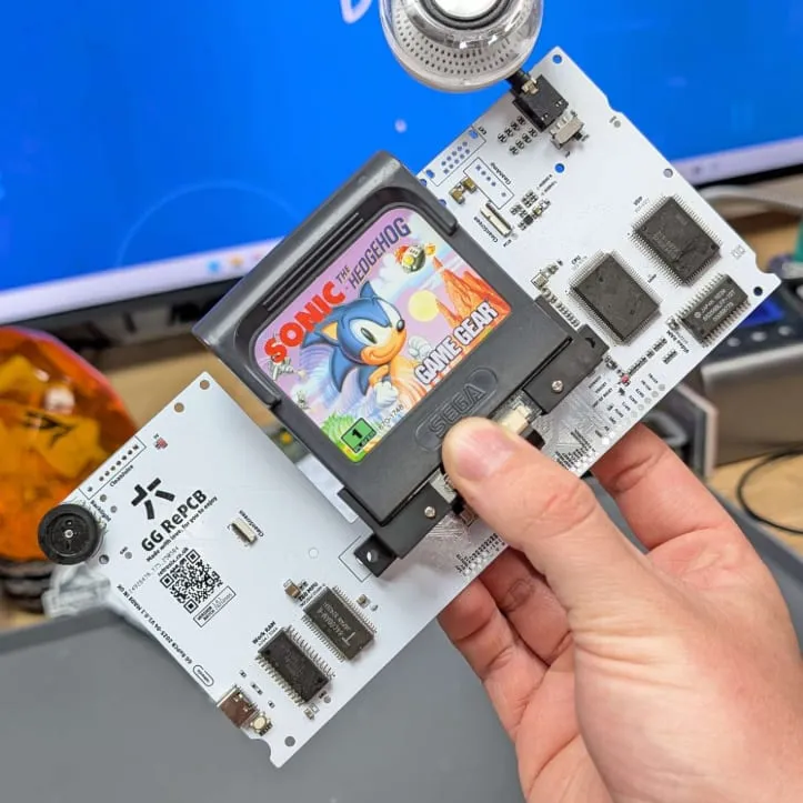
The RePCB is a brand new motherboard for the Game Gear. It supports the CleanScreen as the screen (not the original LCD, sorry) and any power/audio boards. For the CleanScreen install see [GG] RetroSix CleanScreen V4.
Install
Section titled “Install”Transplant your ASICs, MPU and EXT port from the existing console. Then either use a GameSlot or transplant your original cartridge slot.
In short:
-
Solder in the Z80, CPU and VDP, and install an OEM crystal if the custom one is not pre-installed. If you use the OEM crystal, don’t forget to remove the 2 resistors in the black rectangle by the crystal.
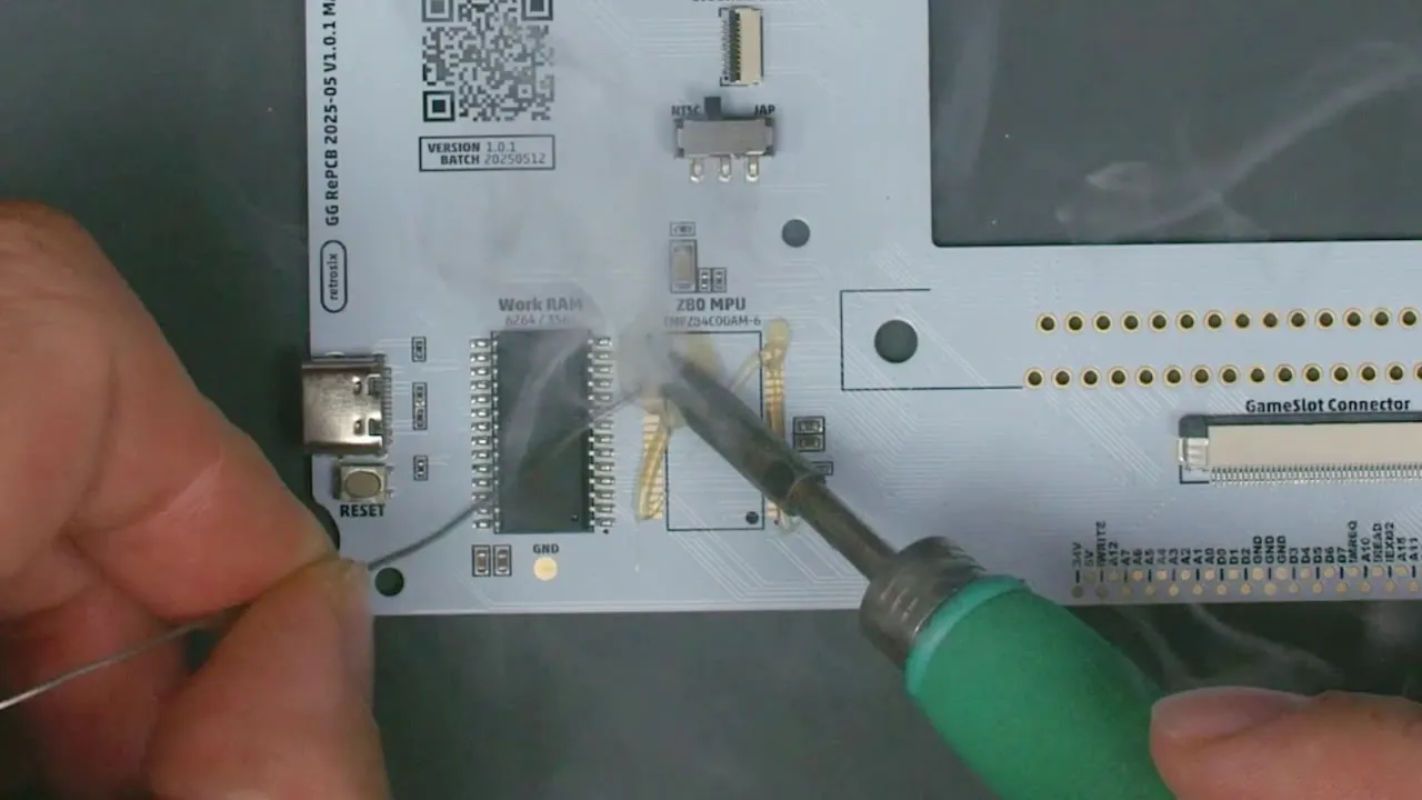
▶ Watch in the video from 1:41
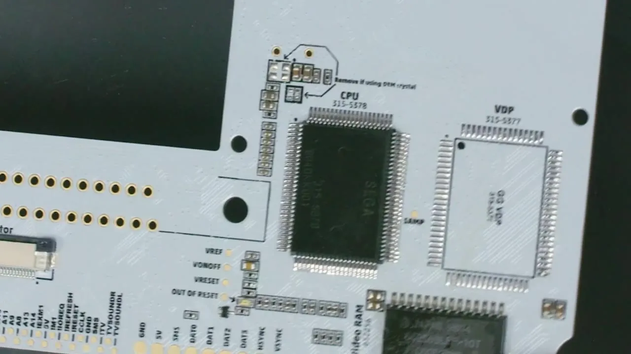
▶ Watch in the video from 8:19
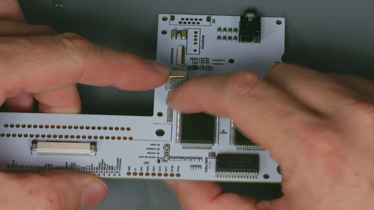
-
Connect a GameSlot with a known working game (or use the original cartridge connector).
-
Power up the console using the USB-C port on the side. Use headphones to listen for the game loading, and press the Reset button by the USB port to reset the game, as initial hot-plugging doesn’t always load a game.
-
Once the game loads and you are happy it’s working, test the CleanScreen, power and audio boards one by one in case any of them introduce issues.
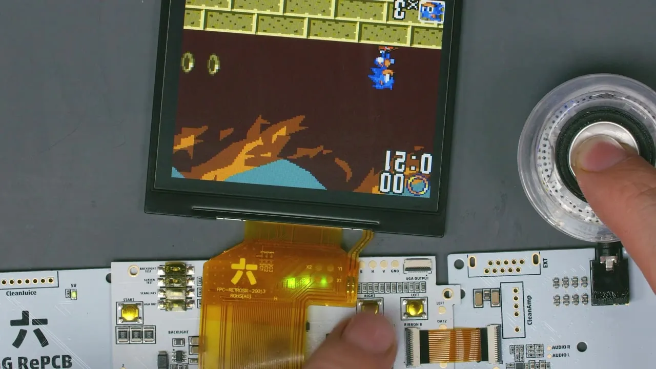
What’s in the box
Section titled “What’s in the box”- Game Gear RePCB motherboard populated with everything except ASICs, MPU, cartridge slot and EXT port
- Brand-new power and audio ribbons
- CleanScreen ribbons
- Solder paste, stencil and spreader to apply solder paste if you want to hot-air the ASICs on
Features
Section titled “Features”- Self-powered: no need for power or audio boards for testing. Simply plug a USB cable and headphones into the ports on the board to fully power up and test the console.
- Reset button to reset the game, useful for bench testing when powering from the onboard USB-C.
- Japan / English toggle switch, accessible from the battery compartment when closed up.
- CleanScreen ribbons for a solder-free CleanScreen install.
- Test points and solder pads for all important signals.
- Improved audio with tones never heard before, thanks to rerouted traces and a new amp and audio filter circuit.
- Out of reset LED, so you know if the ASICs are out of reset.
- Power good LED for the 5V rail.
- Supports the original crystal and a brand new SMD crystal.
- New PCB layout for less noise, cleaner power rails and more accurate data transmission.
- Brand new high-quality SMD components and an improved PCB design fixing faults found in the original.
Identifying floating pins
Section titled “Identifying floating pins”Below are some common symptoms when certain chips or pins are not soldered well.
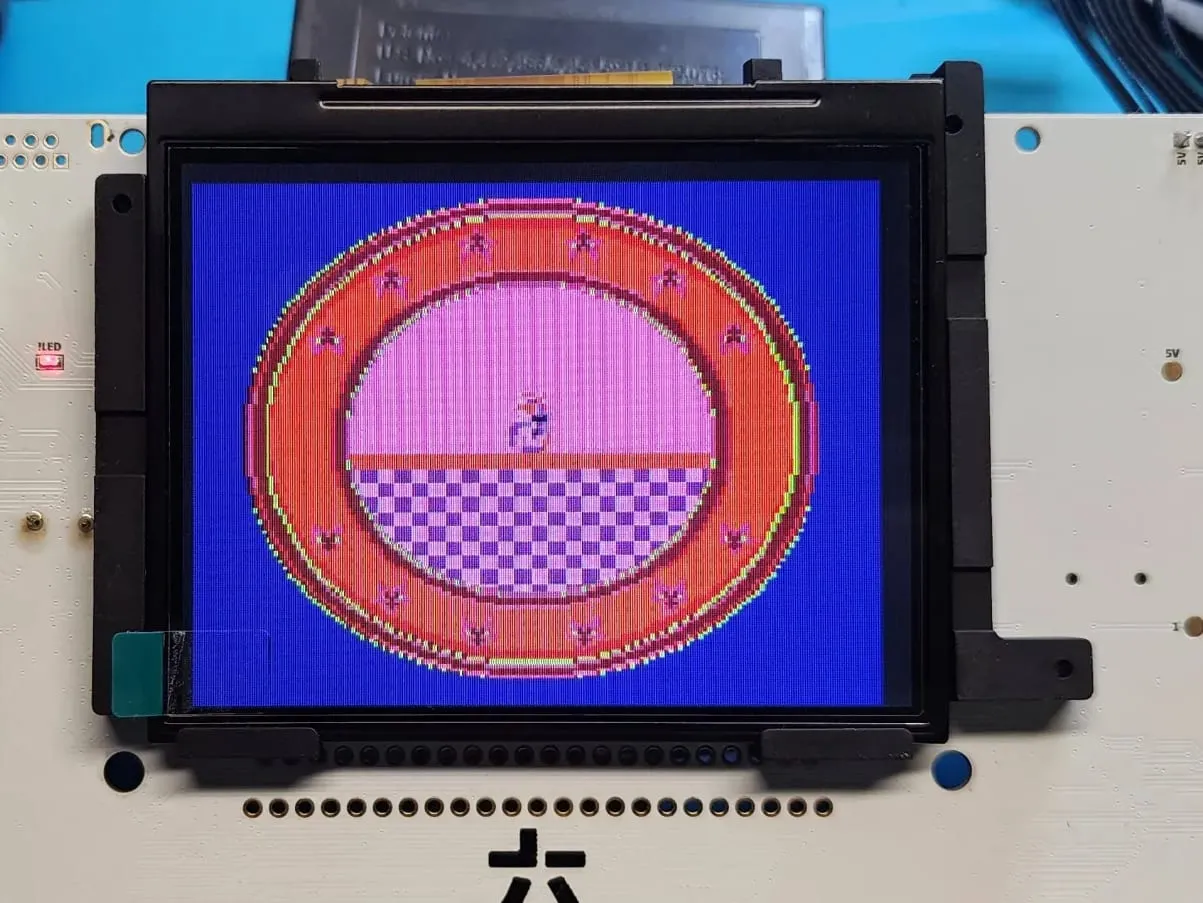
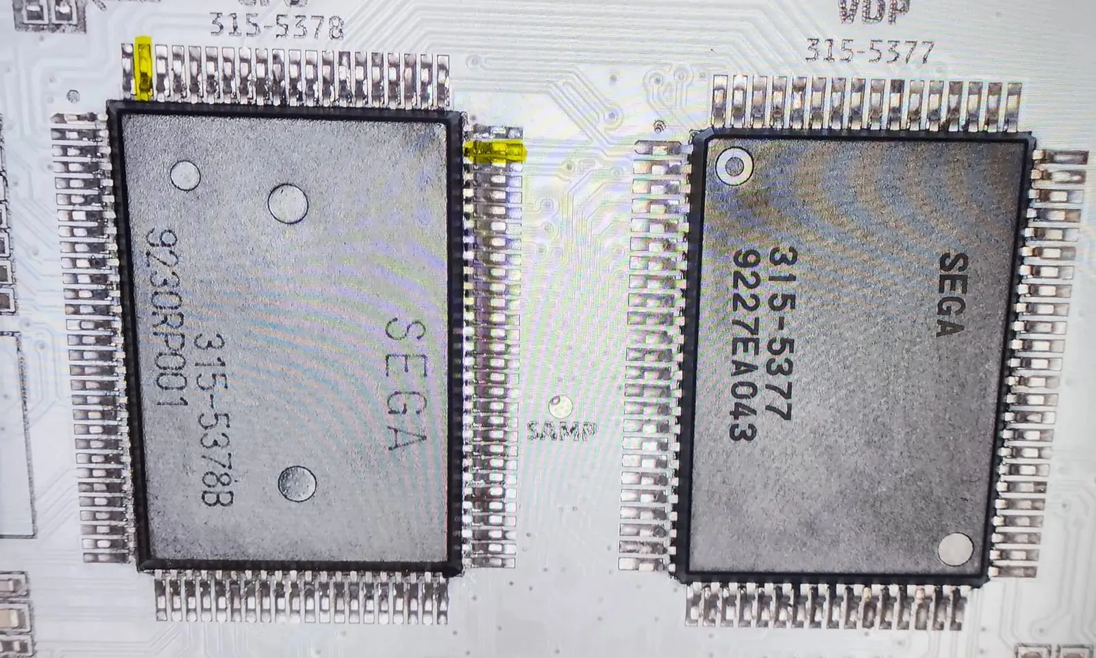
Address pins on the CPU
Section titled “Address pins on the CPU”Caused by A0 and 5V floating on the CPU (and possibly the D3/D4 pins too). Symptom: random colors.
Identifying faulty chips
Section titled “Identifying faulty chips”As these are brand new boards with all new components pre-installed, the only problems you could have if the system doesn’t work using the onboard USB port and headphone jack are:
- A defect in the new RePCB board itself (none so far, so most unlikely)
- A bad GameSlot connection (highly unlikely) or original cartridge port
- A bad game to test with (clean the pins or use a known working game)
- A bad Z80, CPU or VDP, or bad soldering of them (most likely)
So, short of rare exceptions such as bad cartridge slots or games, you are most likely dealing with bad soldering of the Z80/CPU/VDP, or the chips themselves are dead.
The table below lists known failed chips and their symptoms. The number after the faulty chip is how many times RetroSix has personally fixed, tested and confirmed that case. Reports from other users are not counted.
| Out of Reset | Border | Screen Test | Audio | Notes | Faulty chip |
|---|---|---|---|---|---|
| Yes | No | Cyan | No | VDP (3) | |
| Yes | Yes | Cyan | Yes | CPU (1) | |
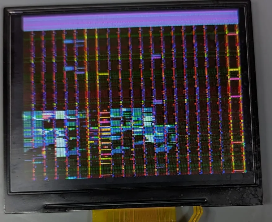
| Yes | Yes | Black | Yes | VRAM-like blocks of corrupt screen pixels | VDP (18) |
| Yes | Yes | Black | Yes | HSYNC/VSYNC pulsing like data pins, causing random screen garble | CPU (2) |
| Yes | Yes | Black | No | GG outputs a random solid screen color such as black, pink, red, dull green, cyan etc. | Z80 (11) VDP (3) |
| Yes | Yes | Black | Yes and no | Nothing on screen other than the black border, or sometimes a fully working screen. On game load, sometimes only the “SEGA” intro sound, other times a full game load. | Z80 (2) |
| Yes | Yes | Black | Missing audio channels | Audio plays but sounds like it’s missing a lot of notes. “SEGA” plays normally. | VDP |
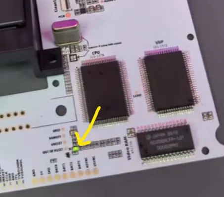
Out of Reset: the Out of Reset LED below the CPU comes on.
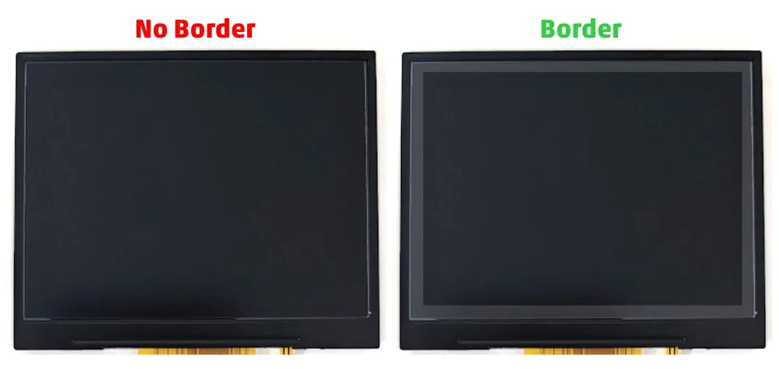
Border: the CleanScreen shows the black border (meaning PCLK, HSYNC and VSYNC are all valid), but the screen stays black.
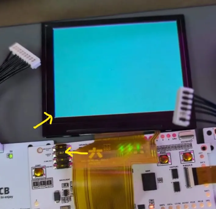
Screen Test: turning on the Screen Test switch on the CleanScreen shows this color (white = all good, red = missing PCLK etc., see here).
Audio: game audio can be heard from the headphone port.
Solid color screen
Section titled “Solid color screen”A common fault is when the screen powers on but just shows a solid color such as black, pink, red, dull green, cyan etc. Unfortunately, this can be caused by almost any chip, including the WRAM, Z80, CPU and VDP. It can also be shorts on the data bus. Ultimately it seems to happen whenever the data bus is corrupt.
However, 95% of the time it has turned out to be the Z80.
Make sure you use a known good working game, clean it beforehand, and check there are no shorts or floating pins on the data bus at the Z80, CPU or VDP.
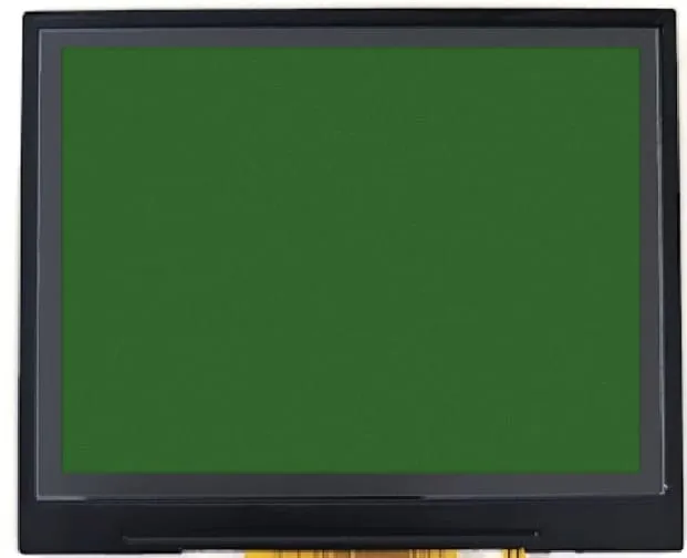
If the Z80 is bad, you often also get the “SEGA” intro sound (sometimes with nothing on screen, sometimes with the game), and the game sometimes loads and sometimes doesn’t. Basically intermittent boot and behaviour.
When the VDP is the cause, the game has never been observed loading.
Bad VDP examples
Section titled “Bad VDP examples”This failed VDP gave VRAM-like errors (noticeable blocks of corruption, not single-pixel corruption).
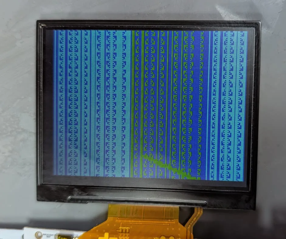
The manufacturer codes of failed VDP chips are collected here, to spot in future whether faulty chips are more common from a particular manufacturing date or factory. So far these are known faulty:
- 315-5377 9229K7 (prevents console boot)
- 315-5377 9214K7 (prevents console boot)
- 315-5377 9215K7 (prevents console boot)
- 315-5377 9211EA009 (boots but corrupt graphics)
- 315-5377 9131E7 (boots but corrupt graphics)
- 315-5377 9138E7 (boots but corrupt graphics)
- 315-5377 9121K7 (boots but corrupt graphics)
- 315-5377 9229K7 (boots but corrupt graphics)
- 315-5377 9141E7 (visually OK, but missing audio channels)
In the video I build a Modern Game Gear in 2025 - The RePCB RetroSix builds a Game Gear with the RePCB 2-ASIC: preparing the board, transplanting the chips from the donor mainboard, fitting the crystal, testing and assembly.