
[GBA] FunnyPlaying IPS 3.0 Laminated Kit
This is the install guide for the FunnyPlaying Laminated IPS 3.0 kit. It has since been updated and replaced by the Laminated IPS M2 3.0 kit.
Video guide
Section titled “Video guide”Getting started
Section titled “Getting started”Take inventory
Section titled “Take inventory”Make sure you have all the parts included with your kit:
Please note: The bracket has been updated and looks like the one in the product photo. Foam is no longer included. You can use Kapton tape to attach the sensor to the back of the LCD.
Before you proceed
Section titled “Before you proceed”- Fully disassemble your Game Boy Advance: Disassembly Guide (GBA Original) (Hand Held Legend)
- Find out whether you have a 32 pin or 40 pin GBA: GBA 32 pin or 40 pin?
- Fully dry test your kit before installation: How do I test the LCD
Install guide
Section titled “Install guide”Optional soldering
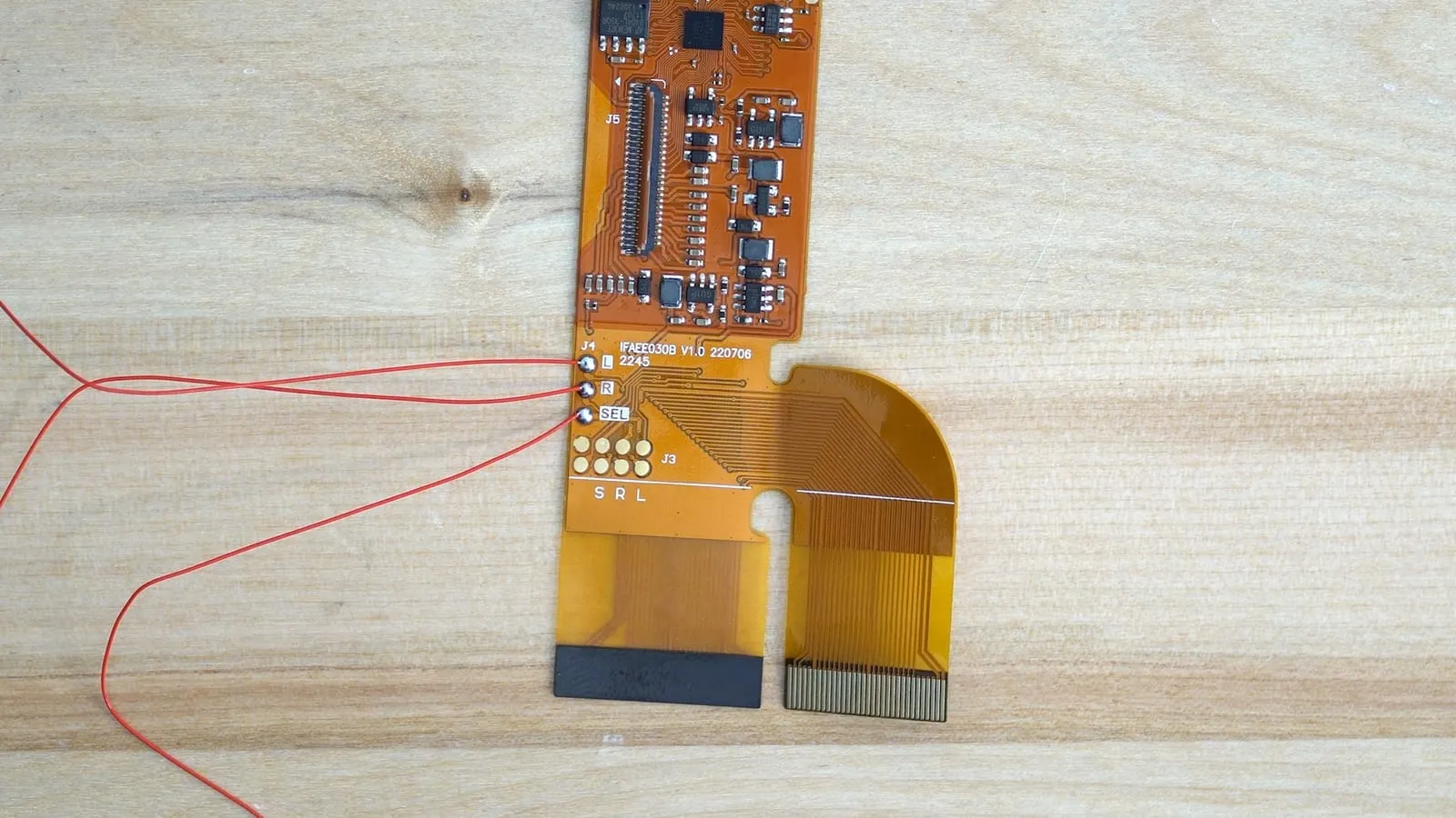
Section titled “Optional soldering”If you want to use the buttons, start by soldering the wires to the flex cable. Use flux, and check out Hand Held Legend’s Soldering Iron Guide if you run into trouble.
Then run the wires to their test points. This can be easier with the ribbon already plugged into the console.
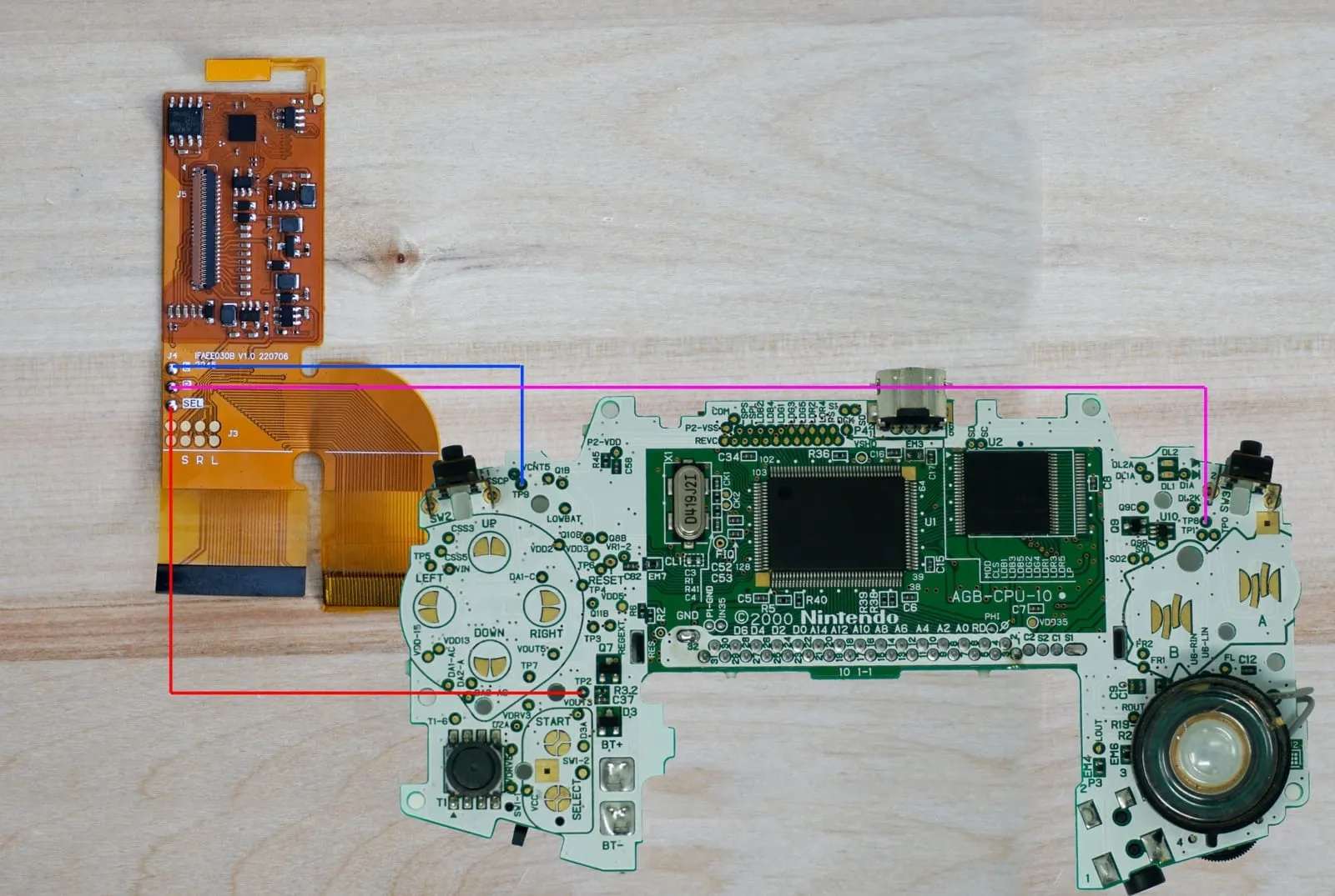
We also recommend putting Kapton tape over the main board pins you won’t be using to prevent accidental shorts.
Prepare the shell
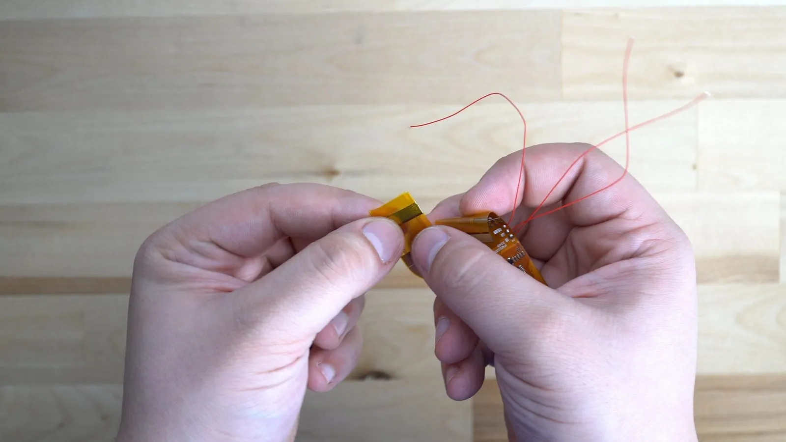
Section titled “Prepare the shell”Once the soldering is done and the spare connector is taped, get the shell ready.
One piece of plastic has to be removed from the shell before the main board can sit in place. Snap it out of the link port area with your fingers before reassembling.
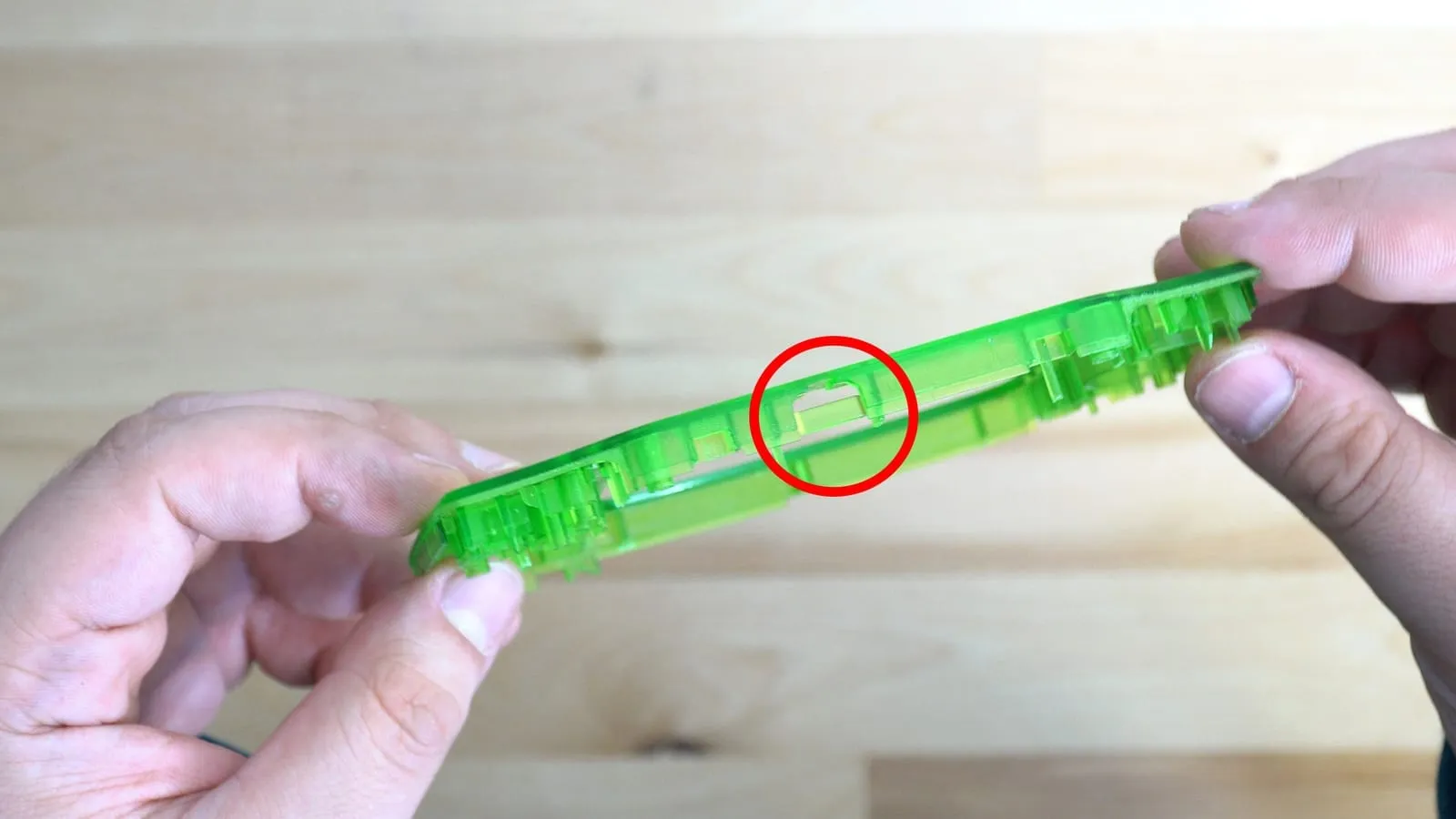
Now the shell is ready for reassembly.
Install the screen
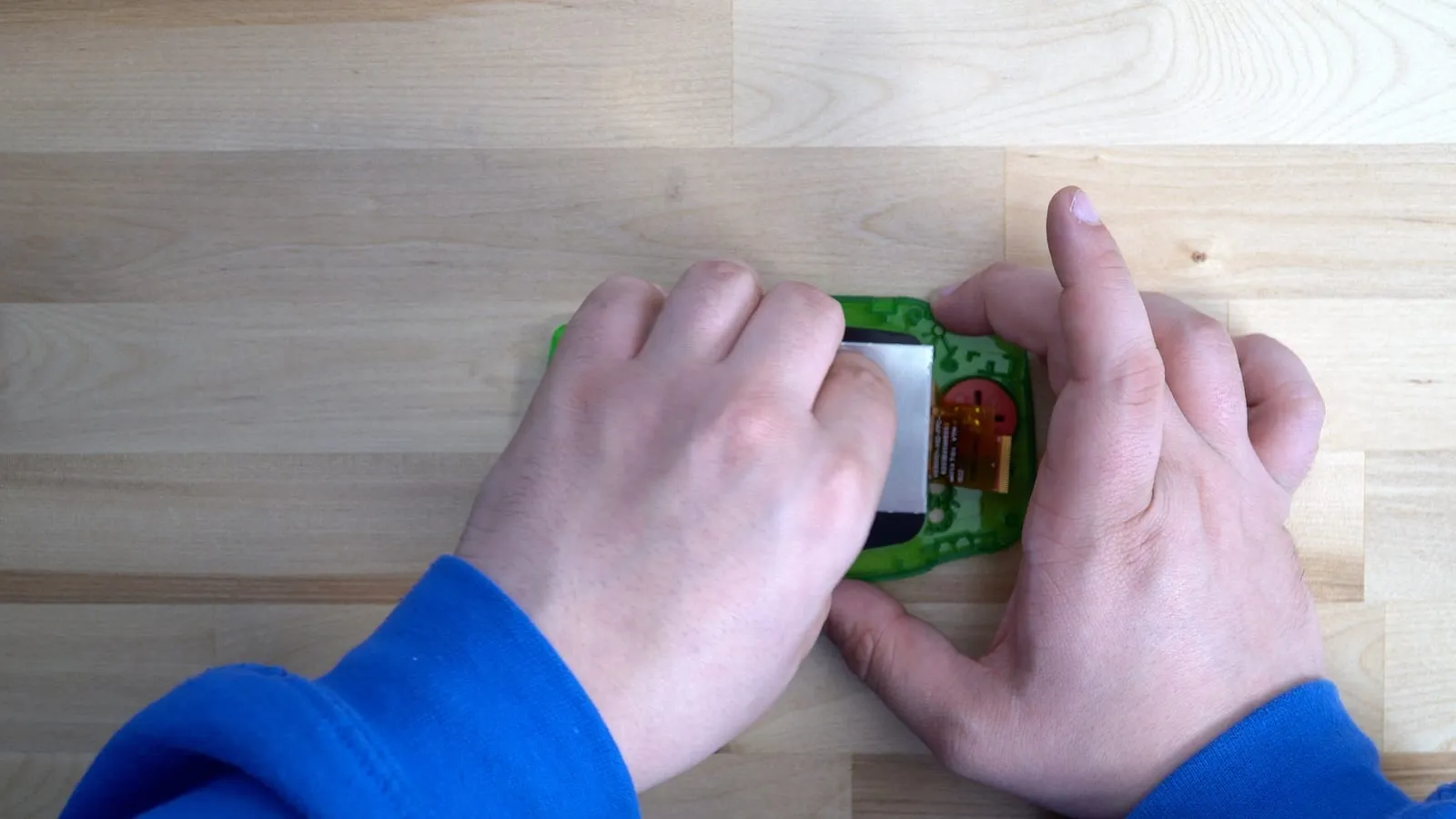
Section titled “Install the screen”Start by placing the screen into the shell. Make sure it sits flush with the shell, otherwise you’ll feel a lip around the screen.
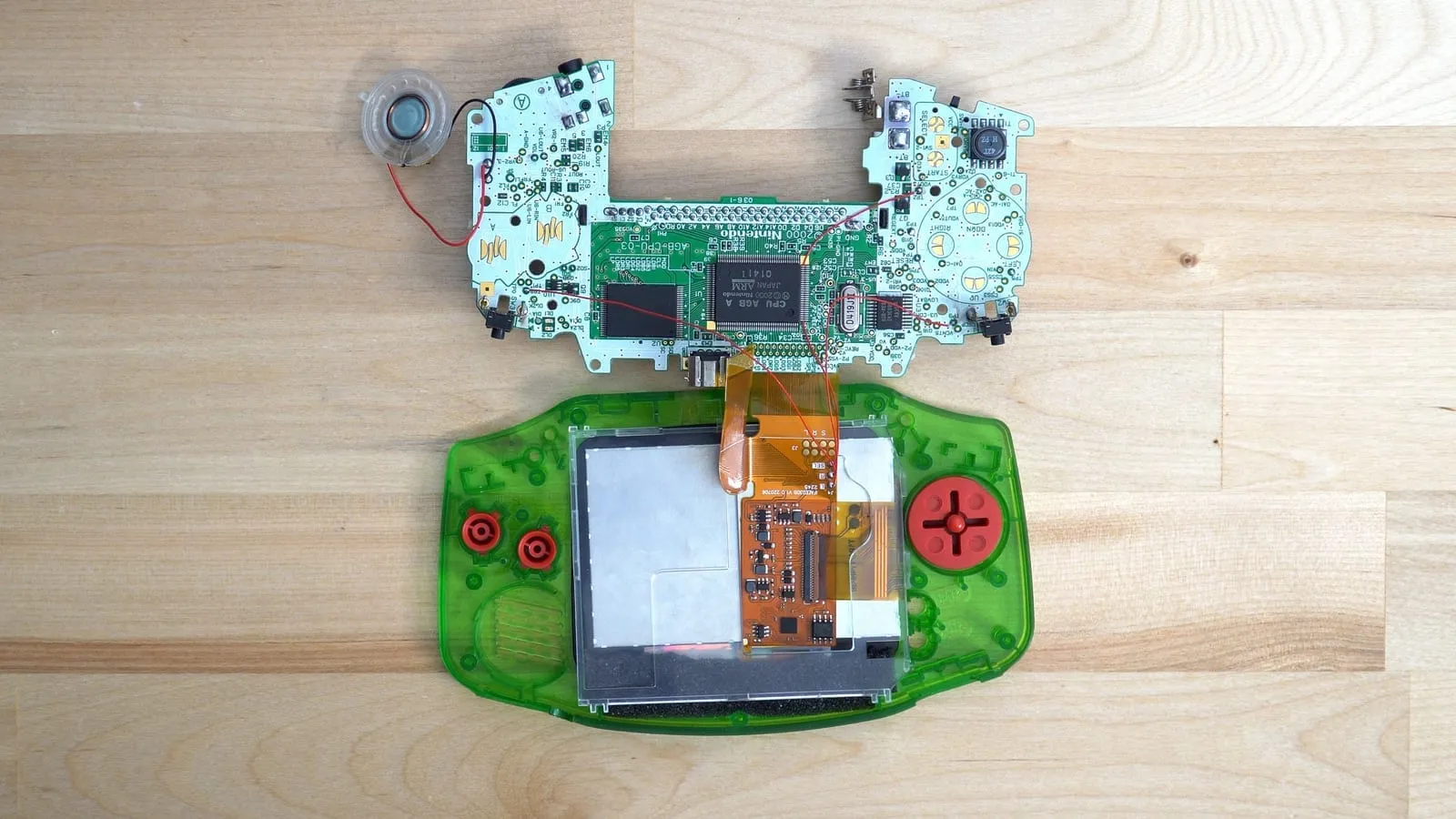
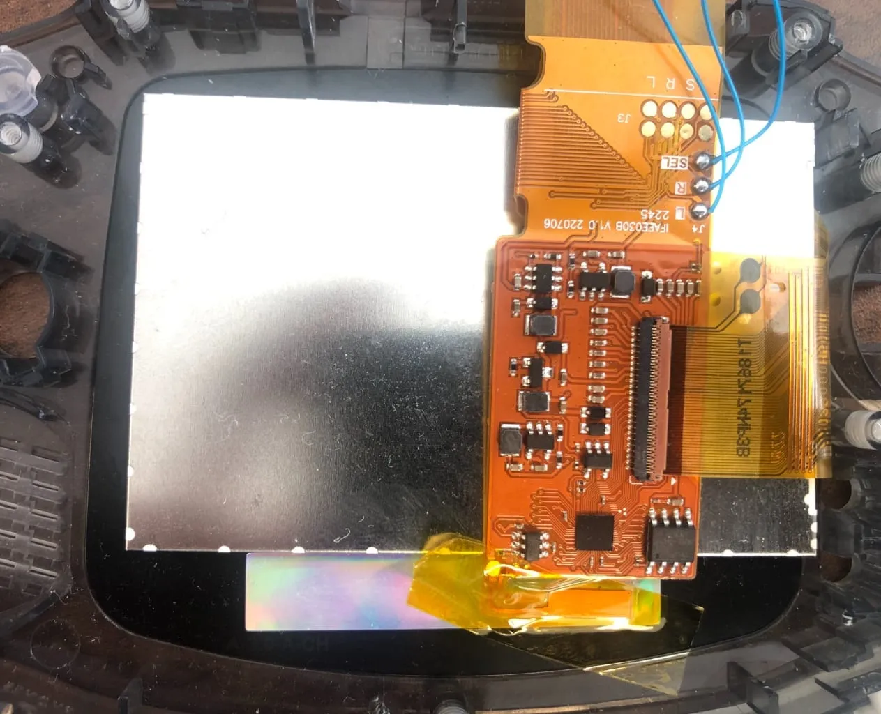
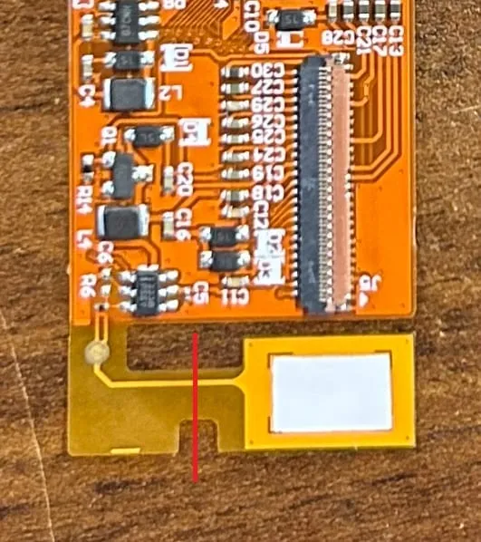
Place the bracket on top of the screen, then feed the bottom of the ribbon cable down to the “Nintendo” logo area, where the touch sensor sits. The kit now comes with a larger touch sensor that has adhesive on the opposite side. You can either let the sensor float freely (not stuck down) and let the bracket hold it, or fold the sensor ribbon in half underneath at the center and stick it down:
Connect the screen’s ribbon cable to the flex cable that goes to the main board. Finally, if you have some, put a trimmed piece of foam over the touch sensor but below the alignment bracket. This holds the sensor against the front of the console. Kapton tape works in place of foam too.
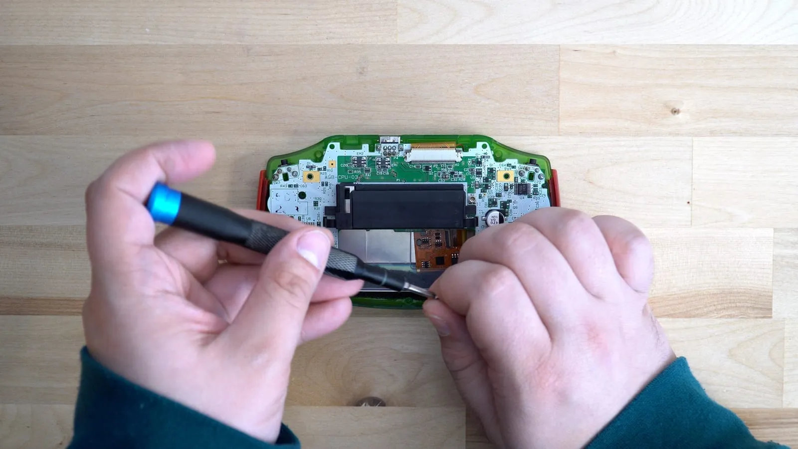
If everything works as expected, finish by replacing the rear screws. See the Disassembly Guide (GBA Original) if you need help.
Using the OSD
Section titled “Using the OSD”The on-screen display (OSD) has several settings, including brightness, color, display mode and frame blending.
To open the OSD, long-press the touch sensor. If you soldered the wires for button control, you can instead press Select, L and R at the same time.
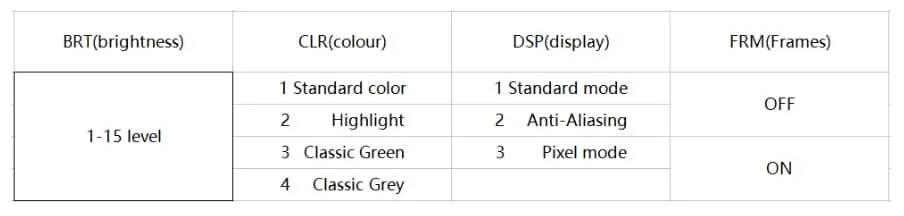
With the touch sensor it’s simple: tap the Nintendo logo once to change the highlighted setting. Long-press the sensor again to switch to the next setting. To exit the OSD, hold the sensor for about ten seconds or let the menu time out on its own.
Troubleshooting
Section titled “Troubleshooting”- IPS Troubleshooting (Hand Held Legend)